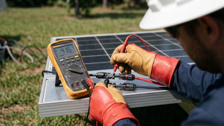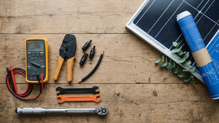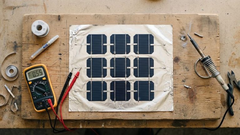
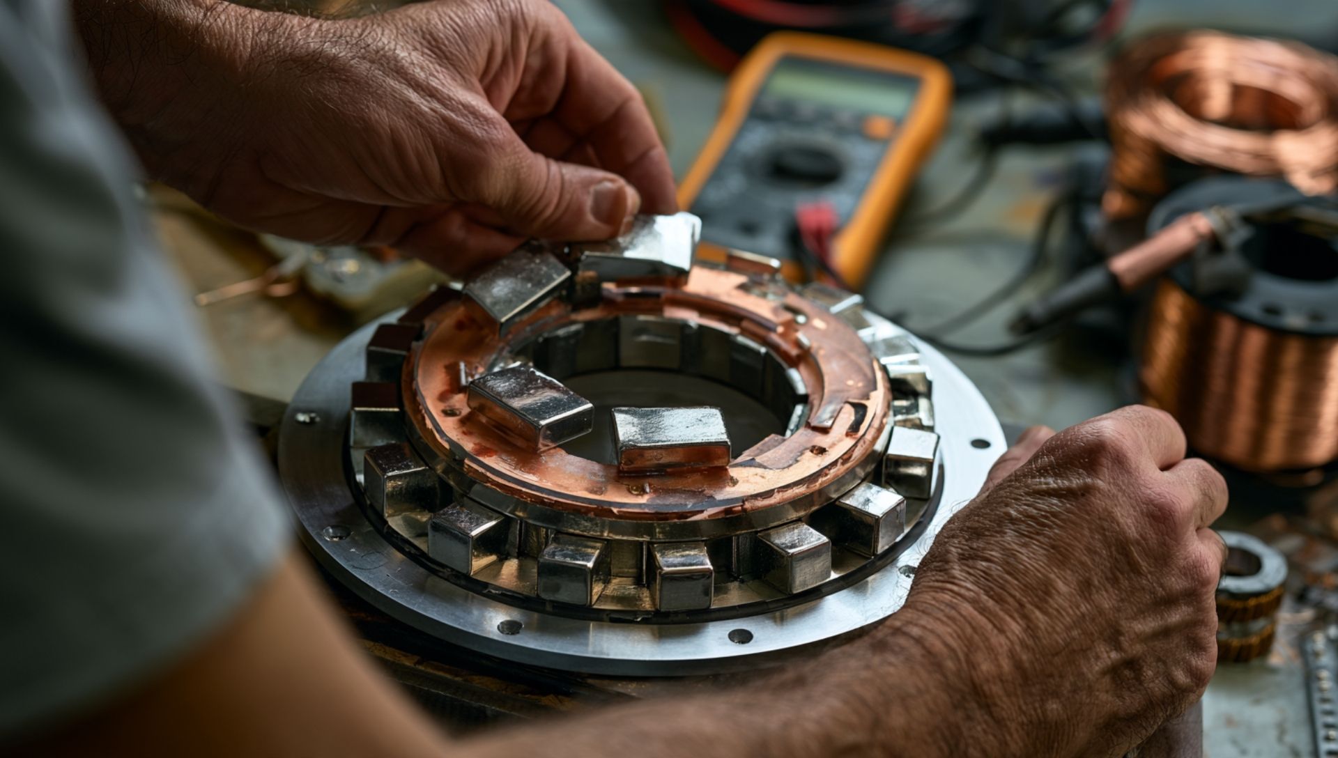
Generating your own off-grid electricity does not require a commercial utility budget or an industrial wind turbine. In fact, the foundational physics powering national power grids is the exact same mechanism you can harness on a workbench: electromagnetic induction. If you want to build an off-grid backup system, design an ultra-efficient micro-hydro generator, or simply understand how magnetic fields move electrons, this comprehensive guide will teach you how to generate power with magnets safely and reliably.
Within this blueprint, you will discover the governing physics of induction, explore permanent magnet generator architectures, review a fully bench-tested DIY build, and learn how to optimize voltage and current output using high-performance neodymium magnets.
Ready to Build Your Own Off-Grid Power System?
The number one reason DIY magnetic generators fail isn’t the physics—it is a lack of precision tools. Don’t drill a single hole or twist a single wire until your workspace is set up like a professional energy lab. Grab our free 17-page blueprint covering the exact tools, safety gear, and air-gap instruments you need to succeed on your first try. (PDF format, No email needed)
The Science of Magnetic Power Generation: How Magnets Produce Electricity
Before building hardware, we must establish a core physical reality: magnets do not contain consumable energy; they are transducers. A magnet does not generate electricity out of nothing. Instead, it acts as a medium that converts mechanical kinetic energy (such as rotating wind blades, falling water, or a hand crank) into electrical energy.
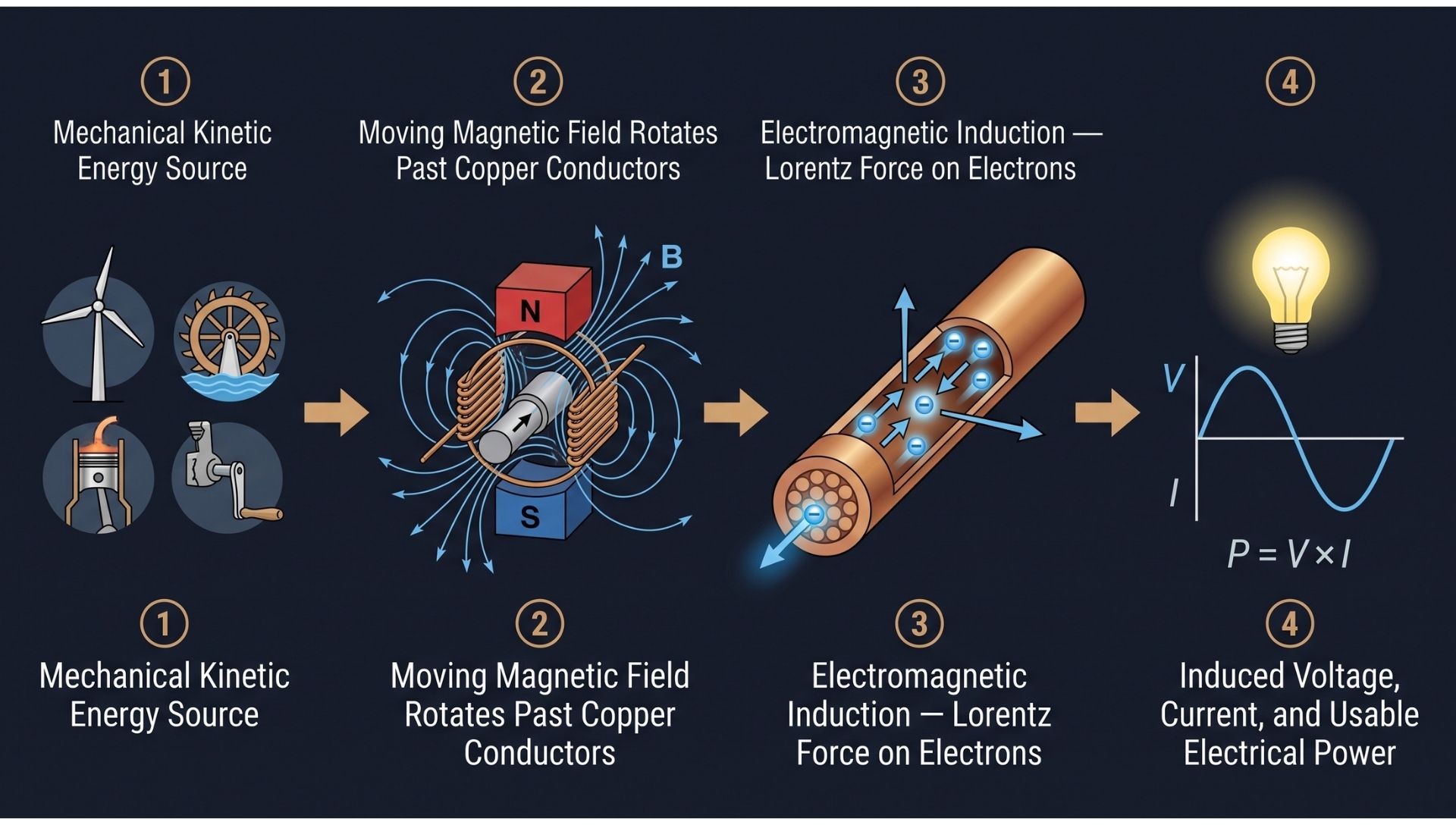
Faraday’s Law of Induction
In 1831, British physicist Michael Faraday discovered the operating principle of modern electrical generation. Faraday’s Law of Electromagnetic Induction states that any change in the magnetic environment of a coil of wire causes a voltage (electromotive force, or EMF) to be induced in the coil:
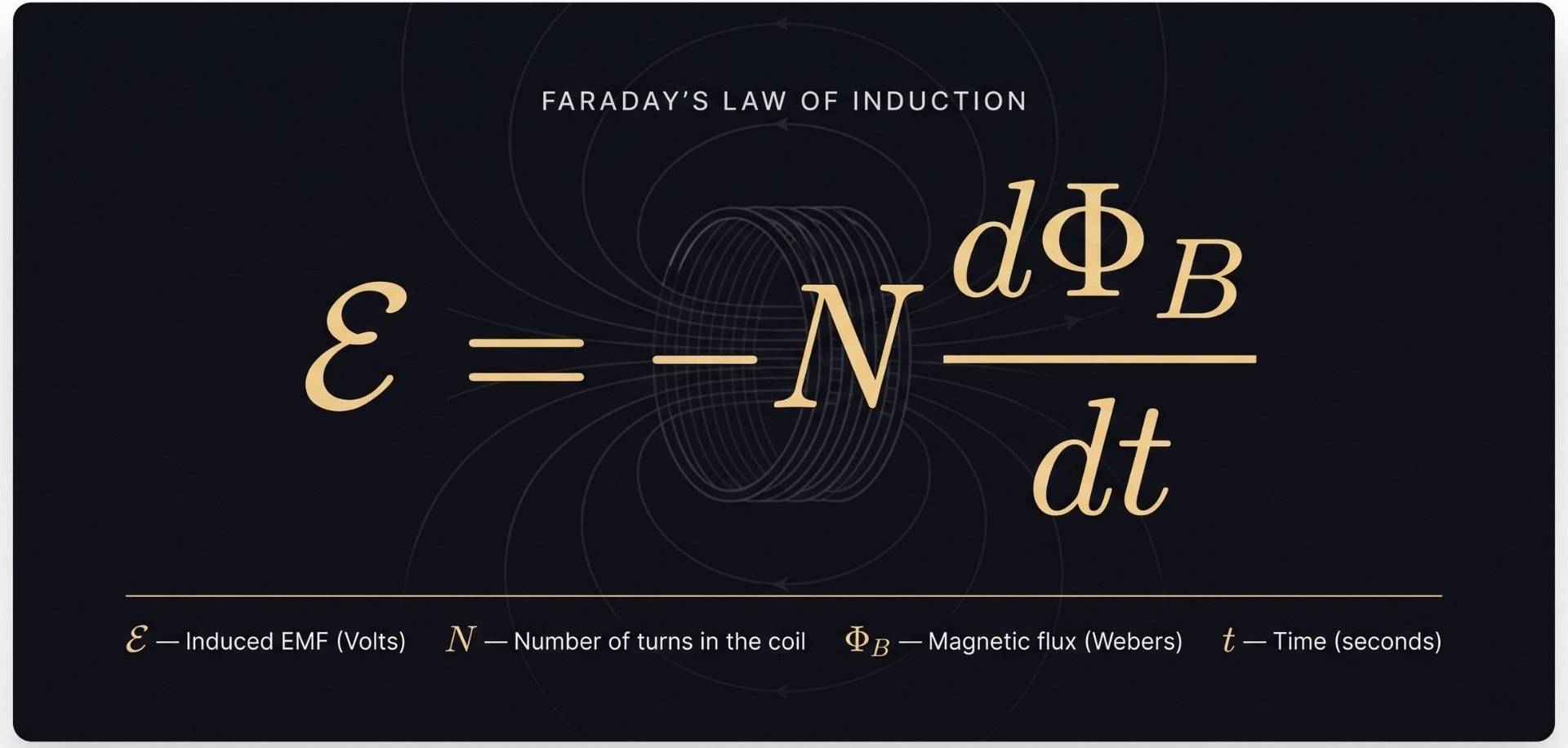
The negative sign in the equation represents Lenz’s Law. It dictates that the direction of the induced electric current always opposes the change in magnetic flux that produced it. When you draw current from a DIY magnetic generator, you will immediately feel mechanical resistance on your rotor. Energy is conserved: the electrical power you harvest directly matches the mechanical force required to turn the shaft, minus heat and frictional losses. Claims of “over-unity” or “free energy” violate the First and Second Laws of Thermodynamics.
How Free Electrons Move in Copper
Copper wire contains a sea of delocalized “free electrons” in its outer atomic valence shells. Under static conditions, these electrons drift randomly in all directions, yielding a net electrical current of zero.
When you rapidly move a strong magnetic field across a copper conductor, the Lorentz force acts on these charged particles:
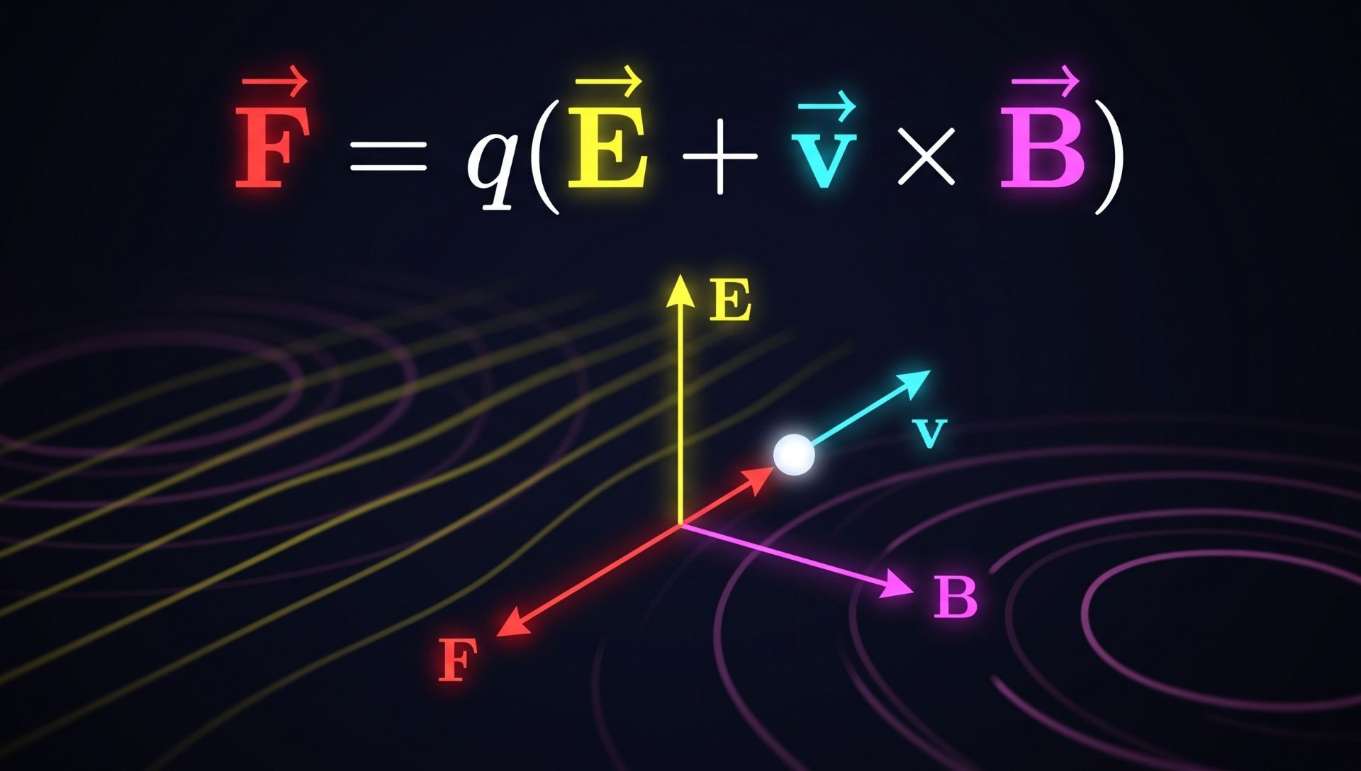
The cross-product (v x B) between the velocity of the moving conductor/magnet and the magnetic field vector exerts a physical push on the free electrons. This pushes them along the length of the wire. This coordinated movement of charge is electrical current.
Speed, Field Intensity, and Flux Density
To maximize the voltage and current when you generate power with magnets, manipulate three key variables:
- Magnetic Flux Density (B): Stronger magnetic fields (measured in Tesla or Gauss) produce a larger shift in flux per cycle.
- Conductor Turns (N): Winding more turns of wire around your coil stacks the induced voltages in series, increasing total voltage.
- Velocity: Doubling the rotational speed (RPM) doubles the rate of flux change over time, which doubles the induced voltage.
2. Types of Magnetic Power Generation Systems
Different mechanical power inputs require distinct generator architectures. Choosing the wrong design creates high mechanical impedance, cogging, or thermal failure.
Permanent Magnet Alternators (PMAs)
PMAs produce alternating current (AC) using permanent magnets embedded on the rotor and stationary wire coils on the stator. They typically feature an iron core inside the coils to concentrate magnetic flux. While efficient, iron cores create “cogging torque”—magnetic attraction between the magnets and the iron teeth when unpowered—making them harder to spin at startup.
Permanent Magnet Generators (PMGs)
While “PMA” and “PMG” are often used interchangeably, a PMG typically incorporates an integrated internal rectifier circuit. This immediately converts the induced alternating current into direct current (DC). This direct output is ideal for 12V, 24V, or 48V battery bank systems.
Axial-Flux (“Pancake”) Coreless Generators
Widely considered the gold standard for DIY renewable energy projects, an axial-flux generator passes magnetic flux parallel to the axis of rotation across a flat, disc-shaped stator. By casting the copper coils in non-magnetic resin (an air-core or coreless design), cogging torque is reduced to zero. The rotor spins freely even in a light breeze, making it the premier choice for DIY wind turbines and micro-hydro systems.
AC vs. DC Output: System Architecture
- Alternating Current (AC): Magnets alternating north-south past a coil naturally produce a sinusoidal AC wave. AC travels long distances with lower resistive line losses.
- Direct Current (DC): Batteries cannot store AC. The raw AC output must pass through a full-bridge diode rectifier to yield DC before charging battery systems.
| Specification / Feature | Axial Flux Coreless (Pancake) | Radial Flux Slotted PMG | Repurposed Car Alternator |
|---|---|---|---|
| Cogging Torque | None (Zero iron resistance) | Moderate to High | Low (when unpowered) |
| Cut-In Wind Speed | Very Low (< 6 mph) | Moderate (8–11 mph) | High (> 12 mph) |
| Peak Efficiency | 88% – 94% | 85% – 90% | 55% – 65% (Lossy field coils) |
| Output Type | 3-Phase AC (requires rectifier) | 3-Phase AC or Rectified DC | 12V–14V DC (Integrated) |
| DIY Build Difficulty | Moderate | High (machining required) | Low (modification only) |
| Ideal Application | Small Wind, Micro-Hydro | Direct-drive Small Wind | Motor-driven test benches |
3. How to Build a DIY Magnetic Generator: Step-by-Step
This build details a dual-rotor, axial-flux, 3-phase coreless generator. It produces stable 12V/24V battery charging power from modest kinetic inputs (like wind or hydro).
EXPLODED ASSEMBLY VIEW (AXIAL-FLUX GENERATOR)
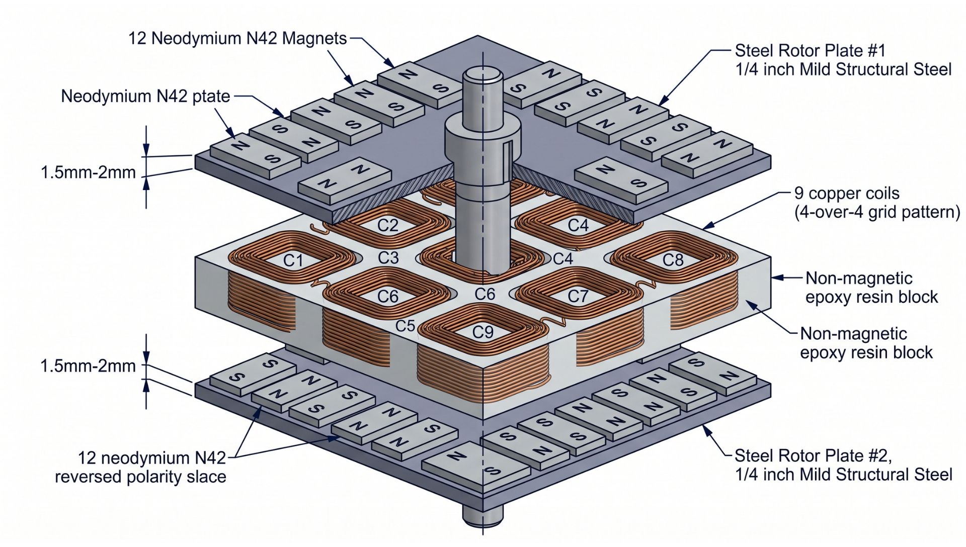
Materials & Tools Checklist
Magnets & Electrical
- Neodymium Magnets: 24 units, Grade N42, rectangular (2 in x 1 in x 0.5 in / 50mm x 25mm x 12.7mm), triple-coated (Ni-Cu-Ni).
- Magnet Wire: 5 lbs spool of 16 AWG (1.29mm) Heavy-Build Polyurethane-Polyamide Enameled Copper Wire.
- Rectifiers: 2 units of 3-Phase Bridge Rectifiers (MDS 100A 1600V modules).
Structural Components
- Rotor Discs: Two 12-inch diameter, 1/4-inch thick mild structural steel plates (mild steel completes the magnetic return circuit; do not use aluminum, wood, or stainless steel).
- Shaft and Hub: 1-inch keyed shaft with heavy-duty cast iron pillow block bearings or a repurposed trailer wheel hub.
- Stator Castings: Two-part fiberglass casting resin/epoxy with hardener; woven fiberglass cloth for tensile support.
Tools
- Digital multimeter (capable of True RMS AC voltage, DC voltage, resistance).
- Hand-cranked or motorized coil winder with mechanical turns-counter.
- Non-magnetic alignment spacers (acrylic, brass, or wood).
- Heavy-duty clamps, safety glasses, and leather work gloves.
Step 1: Winding the Stator Coils
A 3-phase system with 12 magnetic poles requires 9 coils (a 4:3 magnet-to-coil ratio). This ensures phases are electrically separated by 120 degrees, producing balanced three-phase power.
WINDING JIG CONFIGURATION
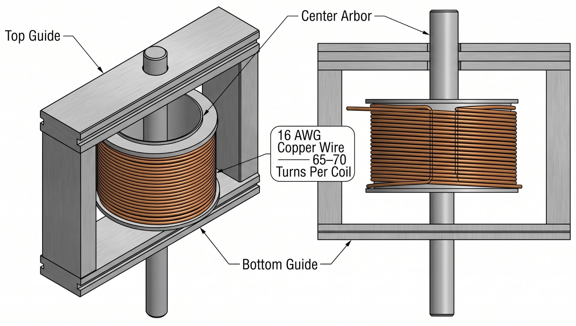
- Construct a wooden or 3D-printed winding bobbin. The center hole must match the dimensions of your magnet face (2 in x 1 in).
- Leave a 6-inch wire lead at the start. Wind 68 continuous turns of 16 AWG magnet wire in tight, flat layers.
- Secure the coil with cyanoacrylate (superglue) or zip ties before removing it from the bobbin.
- Repeat to produce 9 identical coils. Use a digital multimeter to measure the internal DC resistance across each coil. Each should read roughly 0.35 Ω to 0.40 Ω. Discard or rewind any coil that deviates by more than 5%.
Step 2: Wiring the 3-Phase Stator
Arrange your 9 coils in a circle on an acrylic or wax-paper layout board. Divide the coils into three distinct phases: Phase A (Coils 1, 4, 7), Phase B (Coils 2, 5, 8), and Phase C (Coils 3, 6, 9).
3-PHASE STAR (WYE) CONNECTION DIAGRAM
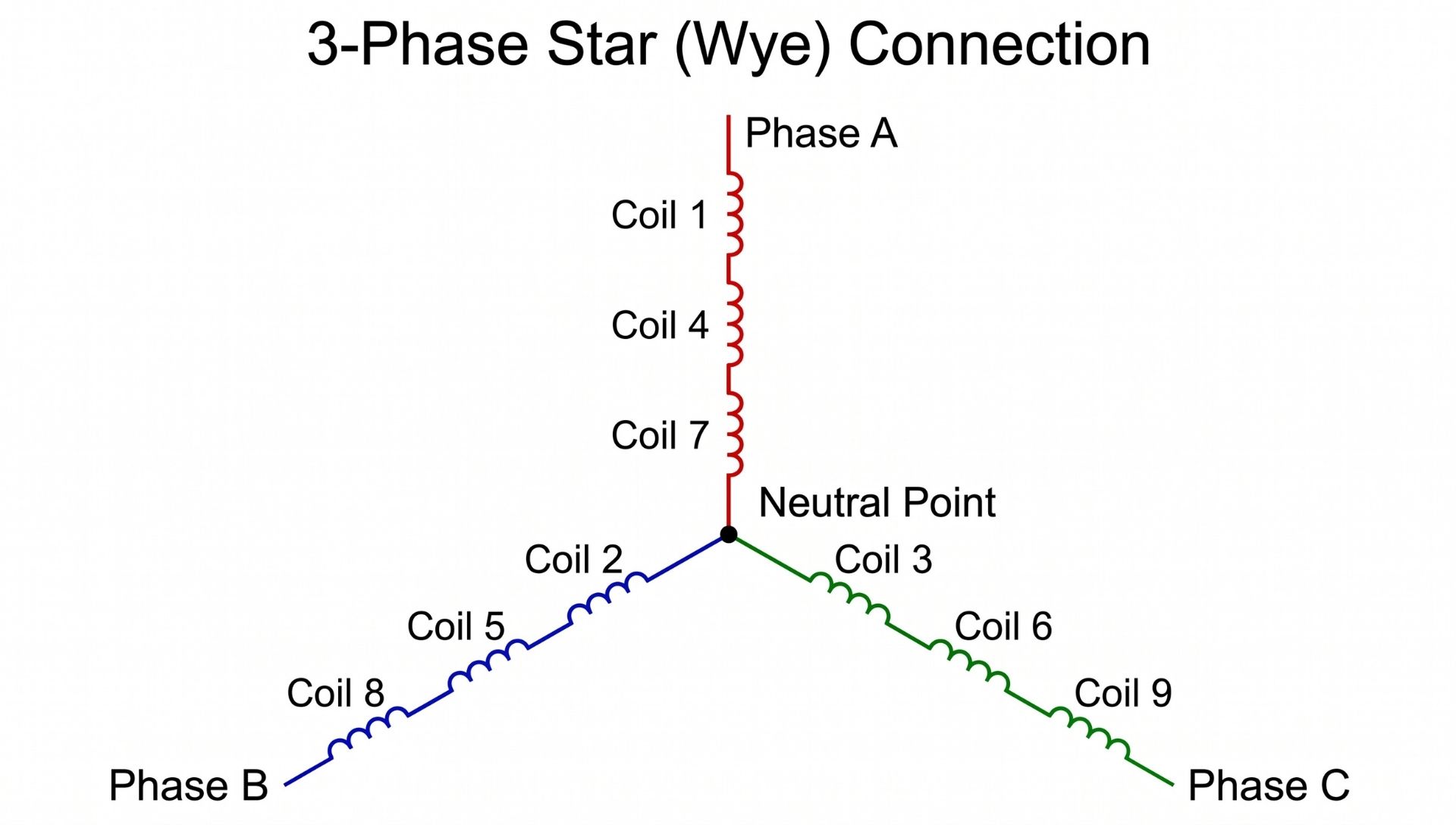
- Connect the three coils of each phase in series: Connect the end of Coil 1 to the start of Coil 4, and the end of Coil 4 to the start of Coil 7. Repeat for Phases B and C.
- Join the three starting leads of Phases A, B, and C together. Solder and insulate this union. This is your Neutral Star Point.
- The remaining three ending leads represent your three AC output phases (L1, L2, L3).
Step 3: Casting the Stator in Resin
To eliminate vibration and protect the copper from moisture:
- Lay a sheet of fiberglass cloth inside a 14-inch circular mold.
- Place the pre-wired 9-coil assembly flat on top of the fiberglass cloth. Route the three AC output wires outside the mold.
- Mix two-part epoxy resin with talcum powder or silica sand (which acts as a thermal conductor to wick away coil heat).
- Pour the resin over the coils until fully submerged to a finished thickness of roughly 3/8 inch (9.5mm). Roll out air bubbles and clamp flat. Allow 24 hours for a full cure.
Step 4: Assembling the Magnetic Rotors
You will mount 12 magnets on each steel plate, alternating polarity: North, South, North, South.
MAGNET ROTOR POLARITY LAYOUT (12 POLES)
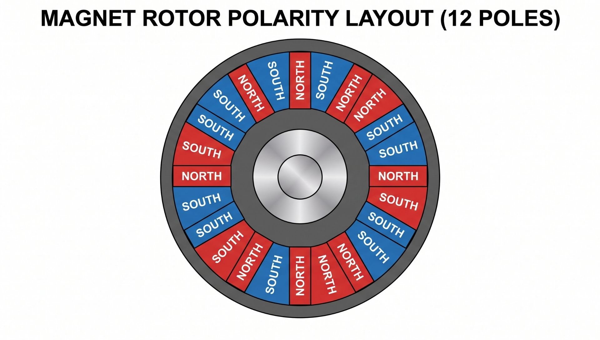
- Scribe 12 evenly spaced radial lines across both mild steel discs using a precision protractor (30°C apart).
- Place the first magnet along the radial line on Disc 1 with its North pole facing outward. Secure it using epoxy.
- Place the second magnet with its South pole facing outward.
- Safety critical: Neodymium magnets will attract each other laterally with dangerous force. Clamp a thick wooden guide block to the plate to prevent magnets from sliding across the disc into one another during curing.
- Populate Disc 2 with an identical alternating array. When the two rotors face each other across the central shaft, align them so opposite poles attract: North on Disc 1 must directly face South on Disc 2. This drives magnetic flux straight through the stator coils.
Step 5: Mechanical Integration and Air Gap Setup
Mount the components along your central keyed shaft:
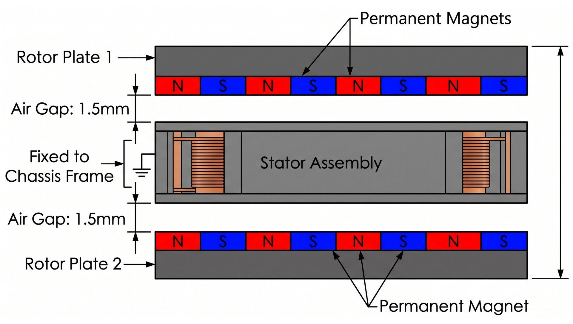
- Mount the stator disc securely to your fixed outer frame. It must not rotate.
- Slide Rotor Plate 1 onto the shaft above the stator.
- Slide Rotor Plate 2 onto the shaft below the stator.
- Adjust the mechanical lock collars so the physical clearance (air gap) between the face of the magnets and the stator is between 1.5mm and 2.0mm per side. Minimizing this air gap maximizes power output, but the plates must not rub or contact the stator during operation.
4. Testing, Measuring, and Optimizing Your Output
Measuring with a Multimeter
- Open-Circuit Voltage (V_OC): Set your digital multimeter to AC Volts (True RMS). Clip the test leads across Phase A and Phase B. Spin the rotor shaft (for example, with a cordless drill locked to 600 RPM). A well-built 12V stator will generate roughly 18V to 22V AC (V_OC) at this speed.
- Internal Resistance (R_phase): Set your meter to Ohms (Ω) and test resistance between any two phase leads. The line-to-line resistance should be low and balanced (< 1.0 Ω).
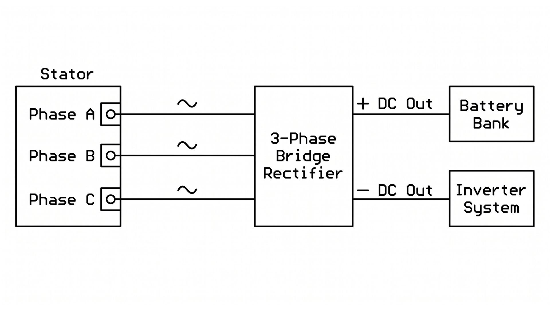
- Rectified DC Voltage: Connect Phase A, B, and C to the AC input terminals of the 3-phase bridge rectifier. Measure the DC output voltage across the positive and negative terminals while under rotation.
Troubleshooting and Diagnosing Inefficiencies
- Output voltage is lower than calculated: Measure your total air gap. A generator with a 4mm air gap can experience a 40% or greater drop in flux density compared to a 1.5mm air gap.
- Rotor plates wobble or vibrate: Your steel rotor plates are not true. Dynamic imbalances at 500+ RPM will cause the magnets to collide with the stator disc, destroying the resin housing. Truing the plates on a lathe or adjusting shaft collars is mandatory.
- Coils get warm under load: Your wire gauge is too thin for the current you are drawing. High electrical resistance ($I^2R$ losses) converts harvestable power into waste heat. Increase the copper conductor cross-section (e.g., step up from 16 AWG to 14 AWG) on your next build.
5. Choosing the Right Magnets: Materials, Grades, and Sizing
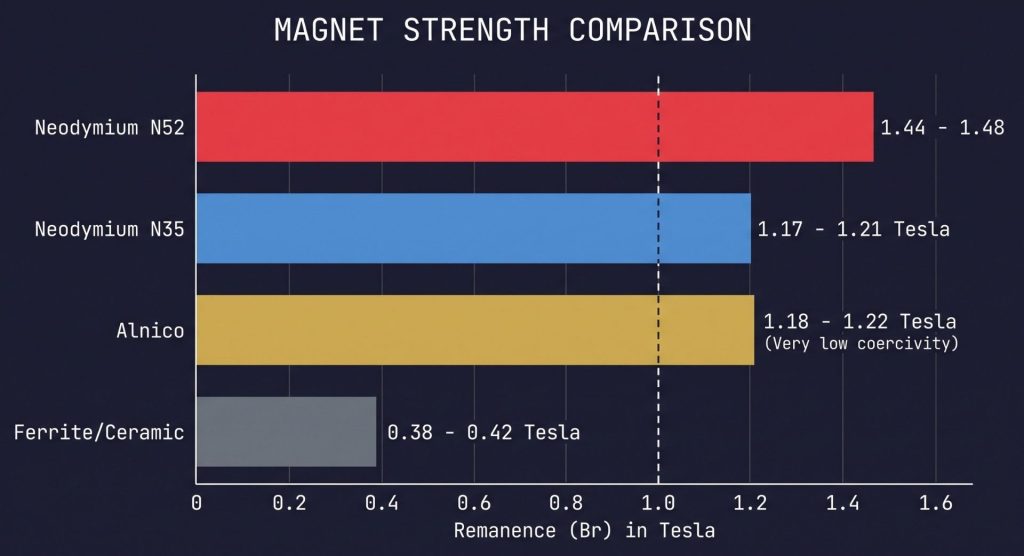
Magnets are not all created equal. Ferrite (ceramic) magnets are inexpensive, but their low flux density requires massive physical arrays to build a workable generator. High-performance projects require rare-earth magnets.
MAGNET STRENGTH COMPARISON
Why Neodymium (NdFeB) Is Superior
Neodymium-Iron-Boron (NdFeB) alloys provide the highest maximum energy product ((BH)_max) commercially available:
- Maximum Magnetic Remanence (B_r): Neodymium magnets output up to 1.48 Tesla (14,800 Gauss), compared to roughly 0.4 Tesla for standard ceramic magnets. A neodymium generator delivers roughly three to four times the power output of an identically sized ceramic system.
- High Coercivity (H_ci): Neodymium resists demagnetization caused by the opposing electromagnetic fields generated inside the stator coils under heavy electrical loads.
Sizing and Selection Matrix
| Grade | Remanence (B_r) | Max Temp (T_max) | Relative Cost | Recommendation |
|---|---|---|---|---|
| N35 | 1.17 – 1.21 Tesla | 80°C (176°F) | Low | Acceptable for low-speed builds |
| N42 | 1.28 – 1.32 Tesla | 8°C (176°F) | Moderate | Optimal balance of power and cost |
| N52 | 1.44 – 1.48 Tesla | 65°C (149°F) | High | Brittle; narrow temperature ceiling |
| N42SH | 1.28 – 1.32 Tesla | 150°C (302°F) | Very High | Best for fully enclosed, hot environments |
- Coating: Insist on Triple-Coated Ni-Cu-Ni (Nickel-Copper-Nickel) or double-epoxy coatings. Exposed neodymium oxidizes rapidly in humid environments, turning the core material to powder.
- Curie Temperature: Standard grades (N35–N52) lose magnetic field strength permanently if heated past 80°C (176°F). Ensure your stator is properly heat-sinked, ventilated, and matched to an appropriate wire gauge.
6. Safety Precautions When Working with High-Strength Magnets
Neodymium magnets designed for generators are not refrigerator novelties. Large N42–N52 blocks exert pinch forces exceeding 100 to 200 pounds (45–90 kg). Mishandling them causes serious crush injuries, broken bones, and flying metal shards.
| WORKBENCH SAFETY ZONE |
| [X] Medical Implants / Pacemakers: Keep > 24 inches (60 cm) away |
| [X] Phones, Laptops, Credit Cards: Keep > 12 inches (30 cm) away |
| [X] Hands & Fingers: Never place between two unconstrained magnets |
| [X] Wear Heavy Split-Leather Gloves and Ballistic Safety Glasses |
| [X] Always Use Non-Magnetic Spacers (HDPE, Wood, Brass) |
Critical Safety Rules
- Pinch Hazard: Never place your fingers, hands, or loose clothing between two magnets or between a magnet and a ferrous steel plate.
- Eye Protection: Neodymium is sintered; it is brittle like ceramic. If two magnets slam together uncontrolled, they will shatter, sending sharp metallic fragments outward at high speeds. Always wear ballistic safety glasses.
- Non-Magnetic Tools: Use brass, aluminum, plastic, or wooden tools during assembly. A steel screwdriver will be yanked out of your grip and driven straight into the magnetic array.
- Medical Device Interference: High static magnetic fields disable the reed switches inside pacemakers and ICDs. Anyone wearing a medical implant must stay at least 24 inches (60 cm) away from large magnet arrays.
7. Future Trends and Integration with Renewable Energy
Permanent magnet generator technology is evolving rapidly, driven by grid-scale decarbonization and electric mobility.
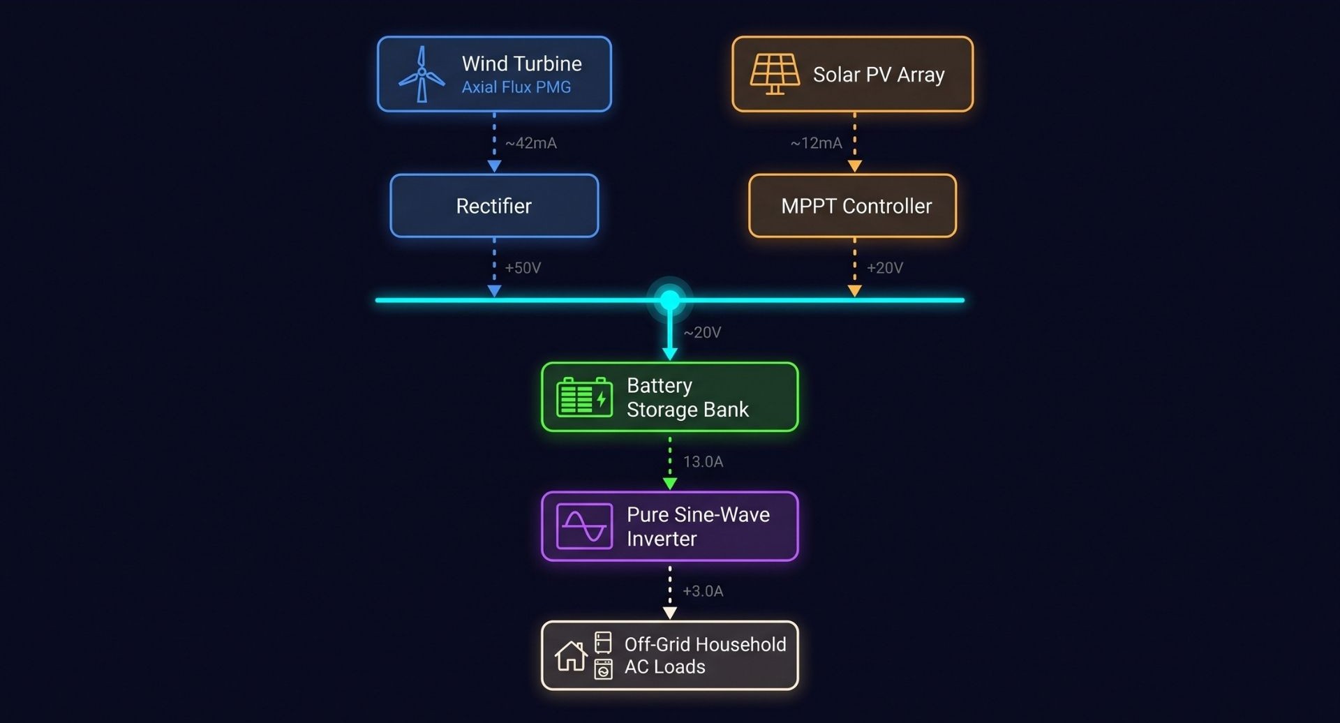
MODERN HYBRID MICROGRID TOPOLOGY
Direct-Drive Wind Turbines
Traditional wind generators rely on complex mechanical gearboxes to step up low turbine blade speeds (15–30 RPM) to high generator speeds (1,500–1,800 RPM). Gearboxes add weight, cause frictional losses, and require frequent oil changes.
Modern commercial installations (pioneered by organizations like the National Renewable Energy Laboratory (NREL)) now use large-diameter, direct-drive permanent magnet generators. The rotor connects directly to the wind turbine blades, eliminating mechanical failure points and boosting efficiency across all wind speeds.
Non-Rare-Earth Magnet Research
Because standard neodymium mining entails significant environmental footprints and geopolitical supply constraints, the U.S. Department of Energy is funding research into next-generation alternatives. Promising candidates include Iron-Nitride (Fe_16 N_2) compounds and optimized Manganese-Bismuth (MnBi) alloys. These alternatives promise high magnetic flux densities with cheaper, environmentally sustainable base materials.
Hybrid Microgrids
DIY permanent magnet generators pair naturally with residential solar photovoltaic systems. Photovoltaic arrays peak at midday during fair weather, while wind and micro-hydro resources deliver steady generation overnight and during stormy seasons. A single common DC bus tie connects both systems to a shared lithium-iron-phosphate (LiFePO_4) battery bank, creating resilient, year-round off-grid power.
8. Frequently Asked Questions (FAQ)
Can a magnetic generator power an entire house independently?
No, not without an external mechanical driver. A permanent magnet generator cannot power a house using magnets alone. It must be coupled to a sustained mechanical energy source—such as a hydro-pelton wheel, wind turbine blades, or a bio-gas engine. Magnets do not contain free energy; they only convert mechanical torque into electrical output.
What is the difference between a permanent magnet generator and a magnetic motor?
The core difference is the direction of energy conversion:
- A generator takes mechanical shaft power in and outputs electrical power.
- A motor takes electrical power in and outputs mechanical shaft power.
Many permanent magnet designs are symmetrical and can run as either a motor or a generator, depending on the operational configuration.
How long do neodymium magnets hold their magnetic charge?
Under normal operating conditions, neodymium magnets lose roughly 1% of their field strength every 100 years. As long as you do not expose them to temperatures above their thermal grade limit (80°C for standard N-grade magnets) or submit them to severe mechanical impacts, they will easily outlast the physical housing of your generator.
What causes “cogging” in magnetic generators, and how do I prevent it?
Cogging torque occurs when the permanent magnets on the rotor are pulled toward the iron cores inside the stator teeth while unpowered. This creates a mechanical “notching” resistance that prevents wind turbine blades from spinning up in low breezes. You can eliminate cogging entirely by designing an axial-flux coreless (air-core) stator, casting the copper coils in non-magnetic resin.
Why do you need three phases instead of just a single phase?
Three-phase stators produce continuous, balanced electrical output with significantly less mechanical vibration. In a single-phase generator, electrical power output drops to zero twice per cycle as the flux changes direction, causing the assembly to vibrate under load. Three-phase systems generate a smooth, constant mechanical load on your rotor and yield flat, high-density DC power when rectified.
What wire gauge should I use when building a DIY magnetic generator?
Your wire choice depends on your project goals:
- Use finer wire (e.g., 20–22 AWG) with more turns to build a high-voltage, low-current system suitable for slow RPM inputs.
- Use thicker wire (e.g., 14–16 AWG) with fewer turns to build a high-current, lower-voltage system for higher-RPM inputs (such as direct-coupled water pelton wheels).
Conclusion: Start Generating Clean Magnetic Power
Learning how to generate power with magnets demystifies off-grid electrical hardware. By moving a magnetic field across a series of copper coils, you put Michael Faraday’s timeless discoveries to work. The keys to building a high-efficiency generator are straightforward:
- Maximize magnetic flux density using properly coated N42 neodymium magnets.
- Keep the air gap between your rotor and stator as tight as mechanical clearances allow.
- Eliminate core cogging through a three-phase axial-flux coreless architecture.
- Respect the laws of thermodynamics: your generator’s electrical output matches the mechanical work you supply to the shaft.
Gather your copper wire, measure your rotor plates, and begin your build. Generating your own clean electricity transforms sustainable living from a theoretical concept into practical self-reliance.
Sources & Further Reading
- U.S. Department of Energy (EERE): How Wind Turbines Work & Generator Mechanics. Available at: energy.gov/eere/wind
- IEEE Transactions on Energy Conversion: Design Methodologies for Axial-Flux Permanent Magnet Machines. Available via IEEE Xplore: ieeexplore.ieee.org
- National Renewable Energy Laboratory (NREL): Advanced Direct-Drive Generator Research for Renewable Microgrids. Available at: nrel.gov
About the Author
David Vance is an electromechanical systems engineer and off-grid technology consultant. Holding a B.S. in Electrical Engineering from Colorado State University, David spent over a decade designing hybrid microgrid installations for remote homesteads and biological research stations. When he isn’t drafting schematic blueprints, he runs hands-on workshops teaching low-impact self-reliance and renewable power fabrication.