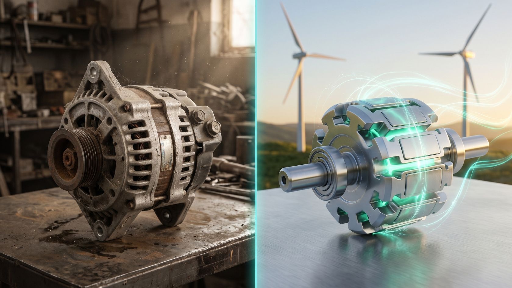
Converting a standard car alternator into a permanent magnet generator (PMA) is a practical way to build a reliable power source for DIY wind turbines or micro-hydro systems. By replacing the electromagnetic field coil rotor with neodymium magnets, you eliminate the need for external battery excitation. The result is a brushless generator that produces power whenever it spins. This guide explains how to select a donor alternator, modify the rotor, safely mount permanent magnets, wire the stator for maximum efficiency, and safely integrate the PMA into your off-grid system.
⚠️ Critical Safety Warning
- Neodymium Magnet Hazards: Rare-earth magnets are dangerously powerful. They can crush fingers if they snap together and will shatter into sharp shrapnel upon impact. Always wear heavy gloves and ANSI-rated eye protection when handling them.
- No Machining Magnets: Never drill, grind, or machine neodymium magnets. The dust is toxic, highly flammable, and the heat generated will permanently destroy their magnetic field.
- Electrical Hazards: An unloaded PMA spinning at high RPMs can produce lethal voltages. Treat all bare wires as live during testing.
- Code Compliance: This guide is for educational purposes. For any permanent or grid-tied installation, consult a qualified electrician and adhere to your local electrical codes (e.g., the NEC).
Key Takeaways
- Function: A PMA generates power without external excitation, with voltage scaling linearly with RPM.
- Core Modification: The stock claw-pole rotor is machined down or replaced, and neodymium magnets are affixed in alternating polarities to induce current.
- Stator Wiring: Rewiring the stator in a Star (Wye) configuration achieves earlier cut-in voltages for low-speed wind turbines; Delta is preferred for high-speed, high-current micro-hydro setups.
- System Integration: Because a PMA has no internal voltage regulation, you must use a heavy-duty 3-phase bridge rectifier and a diversion charge controller with a dump load to protect your battery bank.
What is a Permanent Magnet Alternator (PMA)?
To understand a PMA, you must first understand how a standard automotive alternator works.
In a stock alternator, the spinning rotor acts as an electromagnet. The car’s battery sends a small amount of current through carbon brushes and slip rings into the rotor’s field coil. This generates a magnetic field. As the rotor spins inside the stationary copper windings (the stator), it induces an alternating current (AC), which built-in diodes convert to direct current (DC). The car’s voltage regulator controls the output by adjusting the current sent to the rotor.
The off-grid problem: Standard alternators require high RPMs (often over 1,500 RPM) to generate useful power, and they consume electricity to create their magnetic field. This makes them highly inefficient for low-speed applications like wind turbines.
The PMA solution: By replacing the electromagnetic rotor with a permanent magnet rotor, the generator no longer needs an external power source to create a magnetic field. It becomes 100% self-exciting, generating electricity the moment the shaft turns.
Choosing the Right Donor Alternator
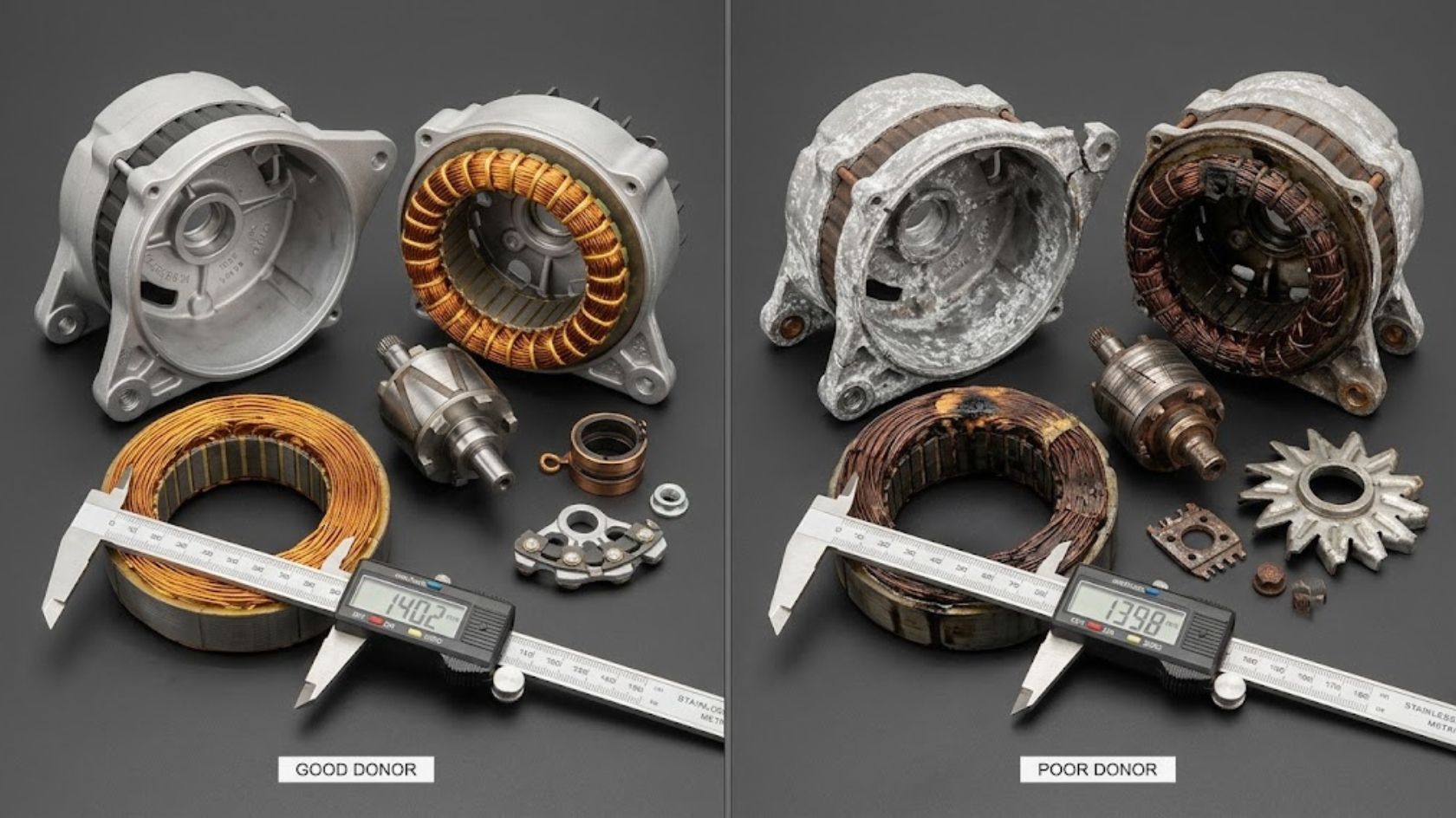
Not all alternators are ideal candidates for a PMA conversion. You want a unit with a large stator diameter (which provides greater magnetic leverage and low-RPM output) and a casing that is easy to disassemble.
- Top Choices: The Delco 10SI and 12SI series are the gold standards for DIY PMAs due to their simple construction, large housings, and the massive availability of cheap aftermarket parts. Large-frame Ford and Bosch alternators are also viable.
- Stator Size: Measure the outer diameter of the stator lamination stack. A larger diameter yields more space for longer copper windings, directly translating to better power generation at lower speeds.
- Pole Count: Count the slots in the stator. A standard automotive stator usually has 36 slots. In a 3-phase system, this equates to 12 coils per phase, meaning the stator is designed for a 12-pole rotor (12 magnets).
Tools and Bill of Materials
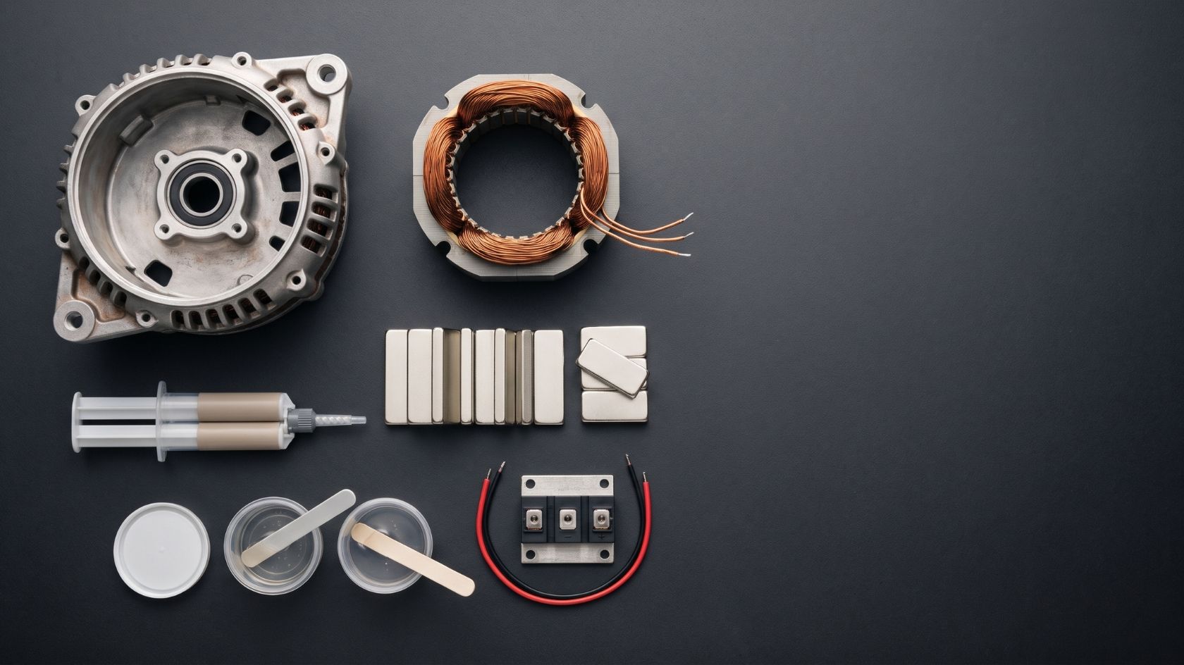
Ensure you have the following components and tools before beginning the build.
Components:
- Donor alternator (e.g., Delco 10SI).
- Neodymium magnets: Grade N42 or N52. Block magnets (e.g., 2″ x 0.5″ x 0.25″) are common. You will need exactly as many magnets as your stator has poles (usually 12).
- Steel for the rotor core (if building from scratch) or the original rotor for machining.
- High-strength structural epoxy (e.g., JB Weld or specialized tooling epoxy).
- Fiberglass tape or Kevlar thread and laminating resin (for banding the rotor).
- 3-Phase Bridge Rectifier (SQL50A or higher) with an aluminum heat sink.
- Optional: Enamel-coated copper magnet wire (if you plan to rewind the stator for different voltage characteristics).
Tools Required:
- Metal lathe (mandatory for machining the stock rotor down to a smooth cylinder).
- Impact wrench and gear puller.
- Angle grinder and drill press.
- Digital caliper and feeler gauges.
- Multimeter.
Step-by-Step Build Instructions
Step 1: Disassembling the Alternator
Use an impact wrench to remove the front pulley nut. Remove the through-bolts holding the alternator casing together. Carefully pry the front and rear aluminum housings apart. Extract the rotor assembly from the center of the stator.
Remove the internal diode pack (rectifier) and the internal voltage regulator. In a PMA, these automotive-grade components are discarded because they cannot handle the continuous duty-cycle and heat generated by a wind turbine or hydro wheel. You will only keep the bare stator (the steel ring with copper coils), the front and rear casings, and the bearings.
Step 2: Modifying or Replacing the Rotor
The stock rotor features interlocking iron “claw poles” wrapped around a copper field coil. To install permanent magnets, you must create a smooth steel cylinder.
- Method A (Machining): Press off the slip rings and cooling fans. Put the rotor in a metal lathe and cut away the claw poles until you are left with a smooth, solid steel cylinder.
- Method B (Fabrication): Fabricate a new cylindrical rotor core out of mild steel, matching the shaft diameter of the original rotor.
Note: The rotor core must be magnetic steel. Do not use aluminum or stainless steel, as they will not carry the magnetic flux between the magnets, drastically reducing your power output.
Step 3: Magnet Layout and Polarity Alternation
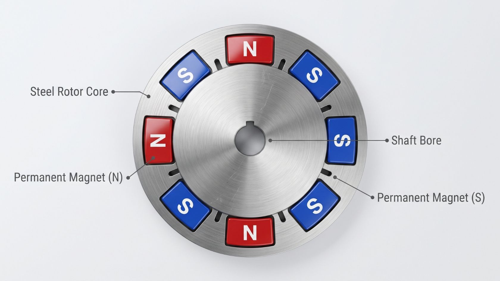
If your stator has 36 slots, you are building a 12-pole machine. You need 12 neodymium magnets spaced perfectly evenly around the steel rotor core.
The most critical rule in a PMA is that magnet polarity must alternate: North, South, North, South all the way around the rotor. If two adjacent magnets have the same polarity facing outward, the generator will not work.
Use a permanent marker to test and label the outward-facing side of every magnet (N or S) before you bring them anywhere near the steel rotor.
Step 4: Mounting and Securing the Magnets
Because neodymium magnets attract each other with bone-crushing force, you must glue them down one by one, using wooden or plastic spacers to keep them perfectly aligned while the epoxy cures.
- Scuff the back of the magnets and the steel rotor surface with sandpaper. Clean with acetone.
- Apply structural epoxy and clamp the first magnet in place. Allow it to cure.
- Repeat for all 12 magnets, verifying alternating polarities.
Banding the Rotor: Epoxy alone will fail under centrifugal force at high RPMs. You must wrap the exterior of the magnet rotor tightly with fiberglass tape or Kevlar thread and saturate it in high-temperature resin. This “banding” locks the magnets in place so they cannot be thrown into the stator at 1,000 RPM.
Step 5: Setting the Air Gap
The “air gap” is the physical distance between the spinning magnets and the stationary steel laminations of the stator.
- A tight air gap (0.010″ to 0.020″) maximizes power output but increases “cogging” (the magnetic resistance felt when the rotor aligns with the stator teeth).
- A wider air gap reduces cogging, allowing wind turbine blades to start spinning in lighter winds, but sacrifices peak power output.
Use a lathe to turn down the cured fiberglass banding until you achieve a uniform air gap of roughly 0.030″. Use feeler gauges to ensure the rotor does not rub against the stator at any point.
Step 6: Wiring the Stator (Star vs. Delta)
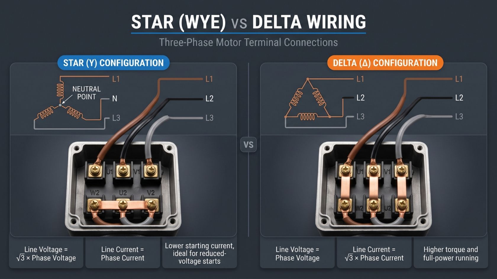
The stator features three separate copper wire phases. How you connect the ends of these three phases dictates your generator’s electrical behavior.
| Feature | Star (Wye) Configuration | Delta Configuration |
|---|---|---|
| Wiring Layout | The ends of all 3 phases are tied together into a common neutral. The 3 starts become the outputs. | The end of Phase 1 connects to the start of Phase 2, forming a triangle. The 3 connection points become outputs. |
| Voltage Output | Multiplied by 1.732. Reaches charging voltage at low RPMs. | Standard voltage. Requires high RPMs to reach charging voltage. |
| Current Output | Standard current limits based on wire gauge. | Multiplied by 1.732. Generates high amperage without overheating. |
| Best Application | Wind Turbines (need to charge batteries at low wind speeds). | Micro-Hydro or Engine Driven (constant high-RPM water flow). |
Related Post: The Ultimate Guide To Vertical Axis Wind Turbines.
Step 7: Rectification to DC
The 3 output wires coming from your stator produce 3-phase Alternating Current (AC). Batteries can only accept Direct Current (DC).
Run the 3 heavy-gauge output wires out of the alternator casing and connect them to an external 3-Phase Bridge Rectifier. Bolt the rectifier to a thick aluminum heat sink, as rectifying high currents generates massive amounts of heat. The two output terminals on the rectifier are your final Positive (+) and Negative (-) DC lines.
Step 8: Reassembly and Clearances
Press the bearings back into the front and rear casings. Slide the rotor assembly inside the stator and bolt the casings together. Spin the shaft by hand. You will feel the magnetic “bumping” of the cogging torque, but you should not hear any scraping or grinding. If the rotor rubs the stator, you must disassemble it and slightly machine down the fiberglass banding.
Performance Expectations and Formulas
Unlike grid power, a PMA’s voltage and frequency are entirely dependent on how fast the shaft is spinning.
Calculating Frequency:
To determine the AC frequency (Hz) at a given speed, use this formula:Frequency (Hz) = (Poles × RPM) ÷ 120
Example: A 12-pole rotor spinning at 600 RPM produces 60 Hz AC.
Voltage and Cut-in Speed:
Open-circuit voltage scales linearly with RPM. If your PMA produces 12V at 300 RPM, it will produce approximately 24V at 600 RPM. The point at which the PMA voltage exceeds your battery bank voltage (e.g., 13.8V for a 12V system) is called the cut-in speed. Below this RPM, the generator produces no usable power for charging.
Application Guidance: Wind, Hydro, and Battery Charging
Charge Controllers and Dump Loads
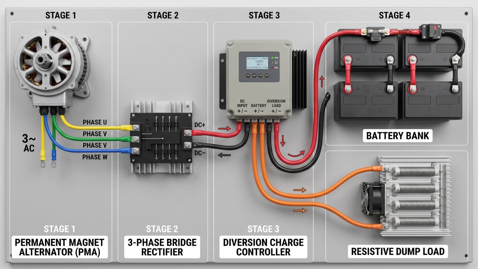
Standard automotive alternators regulate their own voltage. PMAs do not. If a PMA is spinning fast and not connected to a battery, voltage can spike to 100V or higher, frying electronics.
You cannot use a standard solar charge controller with a PMA. If a solar controller disconnects a wind turbine from the battery when full, the turbine loses electrical resistance, over-speeds, and mechanically destroys itself in high winds.
Instead, you must use a Diversion Charge Controller. When the battery bank is full, the diversion controller routes the excess electricity to a “dump load” (usually a heavy-duty resistive heating element in the air or a water tank). This keeps a constant physical load on the turbine blades, preventing over-speeding.
Related Post: Off-Grid Solar Sizing & Cost Blueprint: The Definitive Master Guide.
Troubleshooting Common PMA Issues
- Severe Cogging Torque: If the shaft is too hard to turn by hand, your magnets are too powerful, your air gap is too tight, or your stator teeth are too wide. Some builders skew the stator laminations slightly to smooth out the magnetic transition between poles.
- Low Voltage Output: If the RPM is high but voltage is low, the air gap may be too wide, you may have accidentally wired the stator in Delta instead of Star, or the neodymium magnets were damaged by high heat during assembly.
- Overheating Stator: If the stator is smoking, you are pushing more amperage through the coils than the copper wire gauge can handle. You must either reduce the load, switch to a larger 24V or 48V battery bank (which halves the current for the same wattage), or rewind the stator with thicker wire.
- Uneven Phase Voltage: Measure the AC voltage between the 3 wires (Wire A-B, B-C, C-A). If one pairing is significantly lower, you have a short circuit in one of the stator coils.
Maintenance and Longevity
A well-built PMA is highly reliable because it lacks brushes and slip rings, which are the first components to fail in a standard alternator.
- Bearings: Check and replace the front and rear bearings every 2 to 3 years.
- Heat Sinks: Ensure the rectifier heat sink remains free of dust, debris, and cobwebs to prevent thermal failure.
- Rotor Inspection: Listen for changes in the generator’s sound. Scraping indicates the fiberglass banding is failing or a bearing is worn out, allowing the rotor to shift and strike the stator.
Frequently Asked Questions (FAQ)
Car alternators use electromagnets because a car’s engine speed varies wildly from 800 to 6,000 RPM. An electromagnet allows the car’s computer to constantly adjust the magnetic field strength to maintain a steady 14V output regardless of engine RPM. A PMA’s voltage would spike to dangerous levels at 6,000 RPM.
Yes. Permanent magnet DC motors (like those found in treadmills or e-bike hub motors) operate on the exact same physical principles as a PMA and can be spun mechanically to generate electricity. However, purpose-built PMAs or converted alternators generally offer better weather sealing and heavier-duty bearings for outdoor use.
You need 12 magnets. A 3-phase stator with 36 slots features 12 coils per phase. Matching the 12 coils requires a 12-pole magnetic rotor arranged in alternating North-South-North-South polarities.
Yes. Neodymium magnets come in different grades (e.g., N35, N42, N52). Higher numbers indicate a stronger magnetic flux density. Using N52 magnets will induce more voltage into the stator at lower RPMs compared to N35 magnets, resulting in a lower cut-in speed for your turbine.
Cogging torque is the physical resistance you feel when spinning a PMA by hand. It is caused by the strong permanent magnets attracting themselves to the steel teeth of the stator laminations. High cogging torque can prevent a wind turbine from starting to spin in light winds.
No. The AC voltage and frequency produced by a PMA vary wildly depending on how fast the rotor is spinning. To power standard household appliances, you must run the PMA through a rectifier to create DC, store that energy in a battery bank, and use an off-grid inverter to produce a stable 120V or 230V AC output at a fixed 50/60Hz.
Related post: The Truth About Free Energy Generators: What Actually Works for Off-Grid Living.
Conclusion
Building your own Alternator Permanent Magnet Generator is a rewarding project that sits at the intersection of mechanical fabrication and electrical engineering. By carefully selecting a donor alternator, precisely mounting neodymium magnets, and wiring the stator for your specific energy goals, you can create a rugged, brushless power plant capable of harvesting renewable energy for years. Always prioritize safety when dealing with strong magnets and high voltages, and ensure your external charge controllers are properly sized to handle the raw output of your newly built PMA.