Designing an off-grid cabin electrical layout often trips up DIY builders who treat low-voltage direct current (DC) the same way they treat standard household alternating current (AC). One of the most common and costly mistakes beginners make is undersizing wire gauges for long runs, leading to severe voltage drop, dim lights, and excessive heat buildup. Others skip proper fusing on positive leads or ignore the critical importance of a centralized negative bus bar.
Opting for a 12V DC off-grid cabin lighting system over a conventional 120V AC setup bypasses the heavy energy penalties of running an inverter 24/7. When you strip away conversion losses, simplify your wiring topology, and pair your battery bank directly with modern LED fixtures, you create a robust, highly efficient system that keeps your cabin illuminated through the darkest winter nights without draining your storage bank.
Why 12V DC Is the Smart Choice for Off-Grid Cabin Lighting
When powering a remote retreat, energy independence is everything. Designing around a 12V DC architecture maximizes your available amp-hours while keeping system complexity manageable.
Energy Efficiency and LED Compatibility
Modern LED cabin lighting operates natively on direct current. By using DC-native bulbs and fixtures, you deliver electrons straight from your power source to the diode without needing an intermediate power supply. This eliminates the parasitic power draw inherent to running standard household bulbs through an inverter.
Elimination of Inverter Losses
Traditional AC setups require an inverter to step 12V or 24V DC battery power up to 120V AC. Even high-end, pure sine wave inverters experience conversion inefficiencies ranging from 10% to 15%. Over a year of off-grid living, that wasted energy translates to hundreds of watt-hours lost entirely to heat, requiring larger solar arrays and bigger battery banks just to maintain status quo.
Solar and Battery Compatibility
A 12V DC circuit integrates seamlessly with standard 12V AGM or lithium iron phosphate (LiFePO4) battery banks and standard 12V solar charge controllers (such as MPPT or PWM units). You can wire small solar panels directly through a charge controller to your DC fuse block with minimal hardware, reducing points of failure.
System Simplicity and Cost Savings
Avoiding high-voltage AC components—such as heavy conduit, complex junction boxes, and code-mandated Romex installations—drastically cuts material costs. A low-voltage off-grid electrical system is safer to install yourself, easier to troubleshoot with a basic multimeter, and simpler to expand as your cabin grows.
Tools and Materials You’ll Need
Gathering the right professional-grade components before you begin ensures a clean, reliable installation that will stand up to years of off-grid use.
Wiring and Electrical Components
- 14 AWG and 12 AWG Marine-Grade Wire: Use stranded, tin-coated copper wire (Tinned OFC) to resist corrosion in unconditioned cabin environments. Use 14 AWG for standard lighting drops and 12 AWG for long runs or high-draw circuits.
- Ring Terminals and Butt Connectors: Heat-shrinkable, adhesive-lined connectors ensure a moisture-proof, vibration-resistant physical connection.
- Marine-Grade Fuse Block: A 6-way or 12-way blade fuse block with a negative bus bar keeps your off-grid wiring organized.
- Split Loom Tubing: Protects wire runs passing through wooden studs or behind cabin paneling from chafing.
Lighting Fixtures and Switches
- 12V DC LED Light Fixtures: Puck lights, surface-mount strip lights, or vintage-style 12V Edison bulbs rated for 10V–30V DC wide-voltage ranges to protect against charging spikes.
- DC Rocker Switches: Heavy-duty SPST (Single Pole Single Throw) switches rated for DC amperage loads.
- Inline Fuse Holders: Waterproof fuse holders for auxiliary runs or individual light protection where needed.
Safety and Testing Equipment
- Digital Multimeter: Essential for measuring continuity, voltage drop, and operating current.
- Ratchet Crimping Tool: Ensures a cold-weld crimp on wire terminals that won’t pull loose under vibration.
- Heat Gun: For activating adhesive-lined heat shrink tubing.
- Wire Strippers and Side Cutters: Precision strippers prevent nicking fine copper strands.
Understanding 12V DC Wiring Basics Before You Start
Working with low-voltage DC requires a mindset shift from traditional residential wiring. Because the voltage is low, the amperage must be higher to deliver the same amount of wattage.
Ohm’s Law in 12V Circuits
Ohm’s Law (V = I x R and P = V x I) dictates how your system behaves. To find the current (amperage) drawn by an appliance, divide its wattage by the operating voltage. For example, a 10-W LED fixture operating on a nominal 12V circuit draws approximately 0.83 Amps (10W / 12V = 0.83 A).
Voltage Drop Over Distance
In a 120V AC system, a drop of a few volts is negligible. In a 12V DC off-grid cabin lighting system, losing 1.5 volts across a long wire run means your 12V bulbs only receive 10.5V. This causes LEDs to flicker, driver circuits to overheat, or low-voltage cutoff protections to trip prematurely. Distance is your primary enemy in DC circuits.
Wire Gauge Selection
Thicker wire (lower American Wire Gauge number) has less electrical resistance. Selecting the correct wire gauge ensures your circuits operate safely without turning your wire runs into heating elements. Always reference a certified DC wire gauge ampacity chart before pulling wire through your cabin walls.
Related Post: The Ultimate Guide to DIY Off-Grid Energy Systems (2026)
Planning Your Cabin Lighting Circuit Layout
A meticulous layout prevents headaches during installation and simplifies future maintenance.
Sketching a Wiring Diagram
Map out your cabin floor plan on paper or digital software. Mark the exact locations of your battery bank, central fuse panel, wall switches, and every individual light fixture. Measure the total wire path length from the fuse box to the light and back (the complete loop distance).
Dividing Lighting into Zones
Instead of placing every light on a single circuit, split your cabin into logical zones:
- Kitchen/Prep Zone: High-lumen task lighting over counters and tables.
- Main Living Area: Ambient overhead lighting and reading lamps.
- Bedroom/Loft Zone: Low-draw warm white sconces or reading lights.
- Exterior/Porch Zone: Weather-resistant security and entry lighting.
Calculating Total Load and Safety Margins
Sum the maximum wattage of all LED fixtures assigned to a single circuit. Apply a 20% safety margin (recommended by the National Electrical Code for continuous loads) to ensure your wire ampacity and fuse ratings comfortably exceed peak demand.
Positioning the Fuse Box
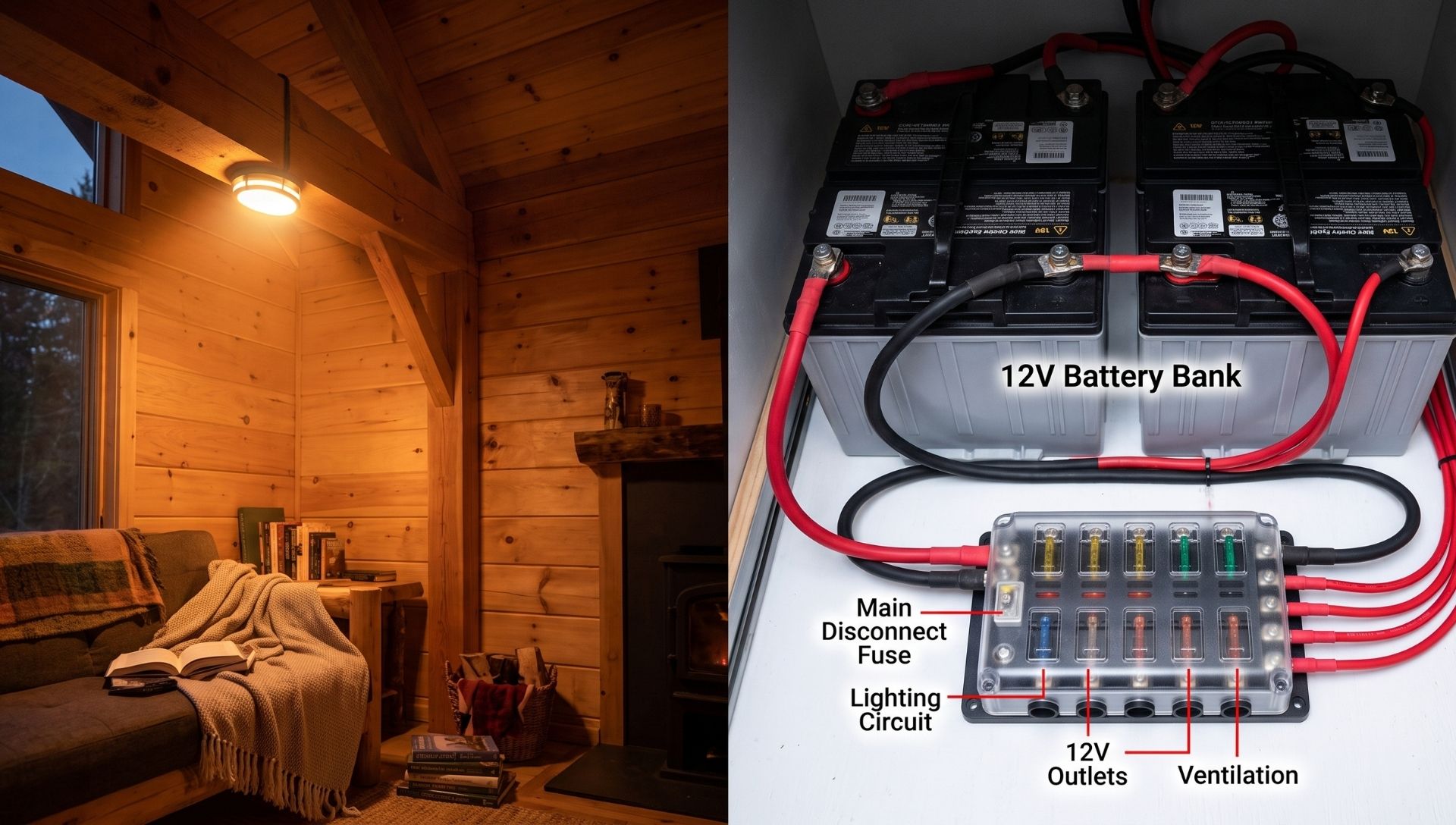
Mount your centralized fuse box or positive/negative bus bar as close to the battery bank as physically possible. Short main feeder cables minimize overall system resistance and reduce voltage drop right at the source.
Step-by-Step Wiring Instructions
Follow these sequential steps to install your 12V DC off-grid cabin lighting system safely and professionally.
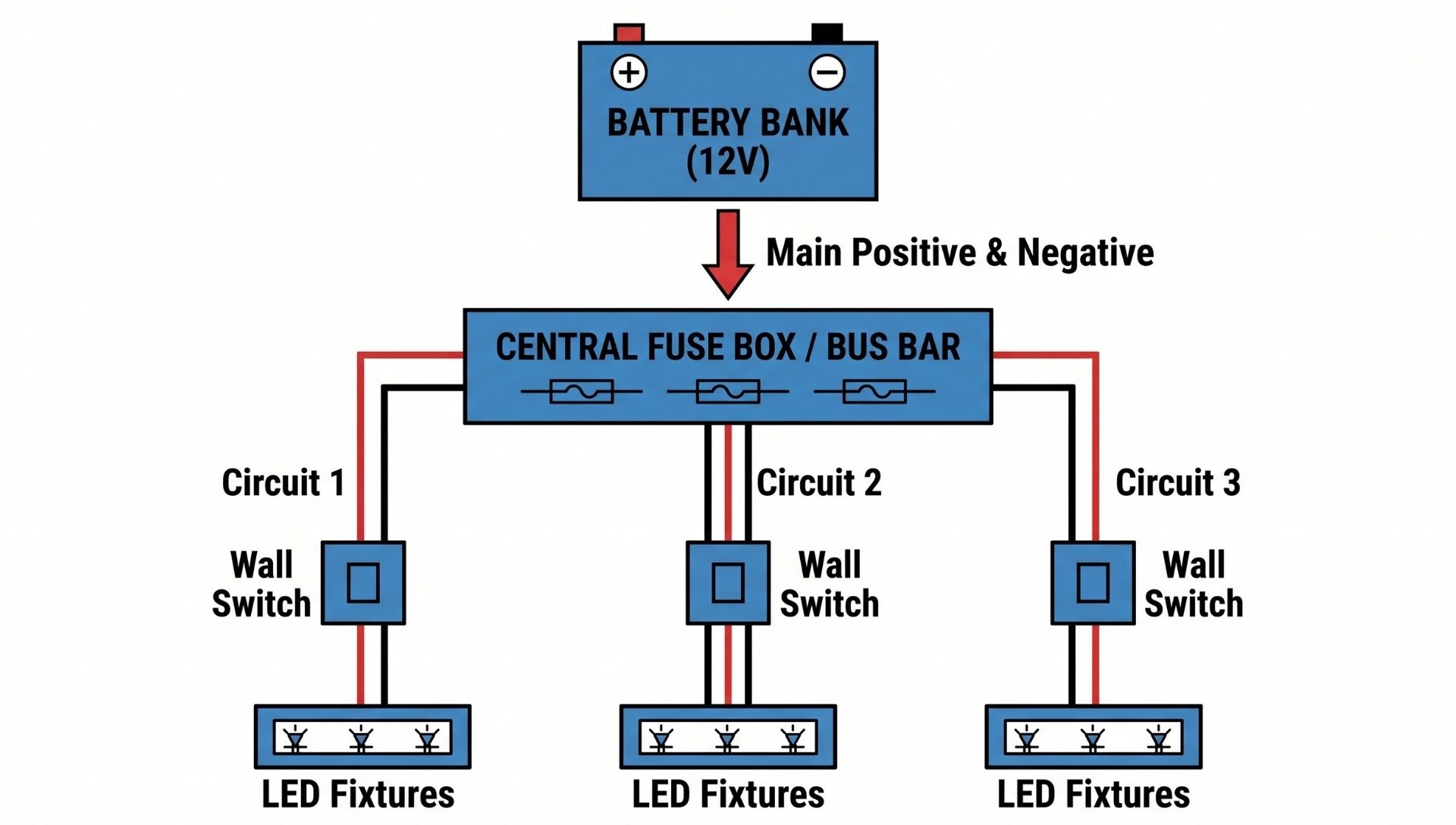
Step 1 — Connect Your Power Source (Battery Bank or Solar Charge Controller)
Begin by ensuring your system is completely unpowered. Disconnect your solar charge controller from the battery bank and switch off any main battery disconnect breakers. Connect heavy-gauge feeder cables (typically 8 AWG or 6 AWG depending on total system amperage) from your 12V battery terminals to your main distribution point.
- Wire Colors: Use red for positive (+) and black (or yellow) for negative (-).
- Torque Specs: Tighten terminal screws to manufacturer specifications (typically 15–20 in-lbs for standard fuse blocks) using a torque screwdriver to prevent high-resistance loose connections.
- Common Mistake: Forgetting to install a heavy-duty master cutoff switch on the main positive line right outside the battery bank.
WARNING: Working around large off-grid battery banks (especially flooded lead-acid or large lithium banks) presents extreme short-circuit and spark risks capable of causing severe burns or igniting hydrogen gas. Always wear eye protection, remove metal jewelry, and use insulated tools.
Step 2 — Install the Fuse Box or Bus Bar
Mount the fuse block securely to a non-flammable backing board (such as plywood mounted to a cabin stud) near your power source. Connect the incoming main positive cable to the main stud of the fuse block, and the main negative cable to the negative bus bar. Ensure all ground paths are tied back to this central distribution point.
Step 3 — Run Your Positive and Negative Wire Runs
Pull your 14 AWG or 12 AWG stranded marine wire from the fuse block out to each designated switch and lighting drop. Secure the wire runs every 4 feet using insulated staples or run them inside protective split loom tubing through bored holes in framing studs. Leave an extra 6 inches of slack at every junction box and fixture location.
Common Mistake: Stapling wires too tightly against wooden studs, which can pinch the insulation and cause a short over time as the cabin settles.
Step 4 — Install Wall Switches
Cut-in junction boxes where you want your wall switches placed. In a DC system, the switch should always interrupt the positive feed traveling to the light fixture, never the negative return. Strip 3/8-inch of insulation from the positive wire coming from the fuse box, insert it into the “IN” or source terminal of the DC switch, and torque it down. Connect the outgoing positive wire leading to the light fixture to the “OUT” terminal.
Step 5 — Connect LED Light Fixtures
At each lighting location, strip the wire ends and connect them to your LED fixture leads using heat-shrink butt connectors.
- Polarity Check: LED lights are strictly polarized. Connecting positive to negative will prevent the LED from lighting up (and can damage cheap internal drivers). Match red-to-red (positive) and black-to-black (negative).
- Use a heat gun to shrink the waterproof tubing around the crimp connectors, sealing out cabin condensation and moisture.
Step 6 — Test Each Circuit with a Multimeter
Before inserting any fuses into the block, switch your digital multimeter to continuity mode (or resistance mode) and test across the positive and negative lines at each fixture to ensure there are no dead shorts in your wiring. Once continuity checks out clear, insert the appropriately sized fuse into the fuse block for that specific circuit, switch the wall switch on, and verify voltage at the fixture reads between 11.8V and 13.6V.
Fuse and Overcurrent Protection: Don’t Skip This
Fuses do not protect your light bulbs; fuses protect your wires. If a wire is pinched or a short circuit occurs, un-fused wiring will draw massive amperage from your battery bank, superheat the copper, melt the insulation, and start an electrical fire inside your cabin walls.
Proper Sizing Based on Wire Gauge
Match your fuse rating strictly to the ampacity rating of the thinnest wire in that specific circuit:
- 14 AWG Wire: Rated for a maximum of 15 Amps. Never use a fuse larger than 15A on a 14 AWG circuit.
- 12 AWG Wire: Rated for a maximum of 20 Amps.
To calculate precise fuse size, multiply the continuous wire ampacity rating by 0.8 (80% rule) or match it directly to the total load plus a safety buffer, provided it does not exceed the wire’s maximum ampacity.
Types of DC Fuses
- ATO/ATC Blade Fuses: Ideal for branch lighting circuits. They are inexpensive, easy to inspect visually, and widely available.
- ANL Fuses: Used as main master fuses between the battery bank and the main distribution bus bar for high-amperage protection.
- DC Circuit Breakers: Convenient for main shutoffs, but ensure they are rated specifically for DC voltage and interruption capacity (AIC), as AC breakers can fail to extinguish a DC arc.
Placement Rule
Place overcurrent protection as close to the power source as humanly possible—ideally within 18 inches of the battery positive terminal.
Voltage Drop Calculations and Wire Sizing for Longer Runs
Let’s walk through a real-world scenario in a larger off-grid cabin: You are running a 20-foot branch circuit (40 feet total round-trip path) carrying a 5 Amp LED lighting load at 12V using 14 AWG wire.
The Voltage Drop Formula

For standard 14 AWG stranded copper wire, the resistance is approximately 2.525 ohms per 1,000 feet.

Evaluating Acceptable Thresholds
For lighting circuits, the maximum acceptable voltage drop is 3% of nominal system voltage (12V x 0.03 = 0.36 Volts). A drop of 0.505V represents a 4.2% drop, which exceeds our threshold and will cause noticeable dimming.
The Solution: Upsizing Wire Gauge
To correct this, step up your wire size to 12 AWG (which has a lower resistance of 1.588 ohms per 1,000 feet):

A 0.317V drop is well within the safe 3% threshold. Rule of thumb: For any branch run exceeding 15 feet in a 12V system, step up from 14 AWG to 12 AWG.
Grounding Your 12V Cabin System Correctly
Proper grounding in an off-grid cabin prevents electrical noise, erratic fixture behavior, and shock hazards.
Negative Bus Bar Strategy
Unlike automotive applications that rely on a vehicle’s steel chassis for the negative return path, an off-grid cabin built of wood requires a dedicated negative return wire for every single circuit. Run paired positive and negative wires side-by-side back to a centralized negative bus bar tied directly to your battery bank.
Floating Ground vs. Earth Ground
In an isolated off-grid cabin installation, your 12V DC system is typically a “floating system”—meaning the negative circuit is not bonded to earth ground unless required by local codes or specific inverter/solar charge controller manufacturer guidelines. However, running a heavy copper earth ground rod tied to your main system enclosure chassis is vital for lightning protection and static dissipation.
Grounding Metal Fixtures
If your cabin features decorative iron, brass, or aluminum light fixtures mounted directly to structural timber, ensure any exposed metal chassis parts are bonded to an equipment grounding conductor to prevent stray currents from creating a shock hazard if wire insulation fails.
Upgrading and Expanding Your System Later
Building flexibility into your initial installation saves you from tearing open cabin walls down the road.
Planning Spare Fuse Slots
When selecting your fuse block, buy one with twice as many slots as you currently need. If you are installing 4 lighting circuits today, buy an 8-way or 12-way block. Those empty slots give you room to grow without rewiring your distribution panel.
Integrating 12V Dimmer Switches
Standard 120V AC household dimmers will instantly fry on a 12V DC circuit. Ensure you purchase PWM (Pulse Width Modulation) 12V DC LED dimmers designed specifically to regulate low-voltage current without generating excessive heat or causing LED flicker.
Adding USB Outlets and Accessory Ports
Since you already have a robust 12V DC distribution backbone, tap into your fuse block to install dedicated 12V cigarette lighter sockets and dual 2.1A/3.0A USB charging ports next to your bed or desk. This allows you to charge phones, tablets, and 12V camping gear efficiently without firing up an inverter.
Common Wiring Mistakes and How to Avoid Them
Even experienced DIYers can overlook subtle details that compromise system integrity. Watch out for these six critical pitfalls:
- Undersized Wire Gauge: Using thin wire over long runs causes voltage drop, dimming, and dangerous wire heating. Fix: Use wire calculators and upsize to 12 AWG for runs over 15 feet.
- Missing Fuse Protection: Running wire straight from a battery to a switch without an inline fuse or block fuse. Fix: Fuse every positive lead within 18 inches of the power source.
- Mixing Wire Gauges Mid-Run: Splicing 18 AWG lamp cord onto 14 AWG main lines creates a bottleneck that generates high resistance and heat. Fix: Maintain consistent gauge throughout the circuit run.
- Incorrect LED Polarity: Forgetting that LEDs only allow current to flow in one direction, leading to troubleshooting panic when a brand-new light won’t turn on. Fix: Double-check positive (red) and negative (black) markings before crimping.
- Loose Terminal Connections: Hand-twisting wires or using cheap electrical tape instead of mechanical crimps. Fix: Use ratchet crimpers, adhesive heat shrink, and torque-checked terminal screws.
- Failing to Label Circuits: Leaving a fuse block unlabeled makes troubleshooting a blown fuse in the dark a frustrating guessing game. Fix: Use a label maker to tag every slot on your fuse block.
Conclusion
Wiring a 12V DC off-grid cabin lighting system is one of the most rewarding DIY projects you can tackle, blending practical carpentry, electrical planning, and energy independence. By respecting Ohm’s Law, calculating wire sizing and voltage drop meticulously, and refusing to cut corners on fusing and bus connections, you establish a resilient, highly efficient lighting grid that will serve your off-grid retreat for decades.
Take your time with the layout, double-check every crimp, and enjoy the clean, quiet brilliance of true energy self-reliance. Want to take your off-grid setup further? Download our free printable off-grid cabin wiring diagram and load calculation spreadsheet, or drop a comment below with your specific cabin layout questions!
Frequently Asked Questions
What wire gauge should I use for 12V cabin lighting?
For standard 12V cabin lighting branch circuits under 15 feet carrying moderate loads, 14 AWG stranded copper wire is the standard choice. For runs exceeding 15 feet or circuits carrying higher amperage loads, step up to 12 AWG wire to minimize voltage drop and maintain full bulb brightness.
How do I size fuses for a 12V DC lighting system?
Fuses must be sized to protect the wire, not the appliance. Match your fuse rating directly to the safe ampacity rating of your wire gauge—such as a maximum 15A fuse for 14 AWG wire and a 20A fuse for 12 AWG wire—while ensuring the fuse rating comfortably exceeds the total operating amperage draw of the connected LED fixtures.
Can I use standard AC light switches for a 12V DC system?
While some household AC switches can handle low-voltage DC loads, standard AC switches are rated for rapid arc quenching at high voltages, which differs from DC arcs that tend to sustain themselves. It is always best practice to use heavy-duty switches explicitly rated for DC electrical applications to prevent pitting and switch failure over time.
How far can I run 12V wire without experiencing voltage drop?
To keep voltage drop within the recommended 3% threshold for lighting circuits, you should generally limit 14 AWG wire runs carrying standard loads to under 15 feet total round-trip distance. For longer runs between 15 and 30 feet, upgrading to 12 AWG or thicker wire is necessary to prevent noticeable dimming.
Do I need a ground wire for 12V DC cabin lighting?
Unlike AC systems that rely on an earth ground for fault clearance, an off-grid cabin DC system requires a complete dedicated negative return wire (paired alongside your positive wire) running back to a central negative bus bar. An earth ground rod is still recommended for system lightning protection and chassis bonding, but it does not replace the physical negative circuit return wire.