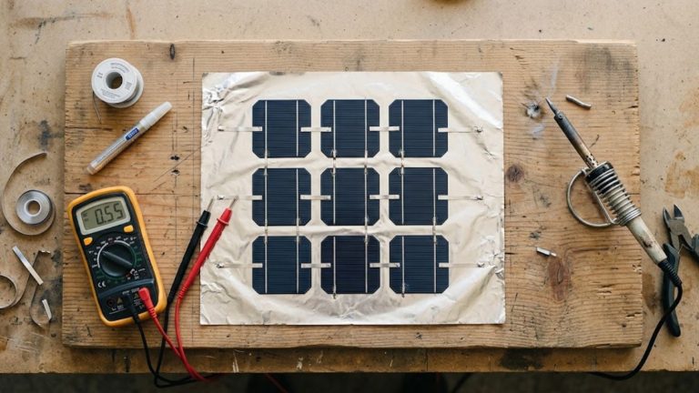
When I first attempted to build a permanent magnetic generator for a backyard off-grid wind turbine over a decade ago, I made nearly every mistake in the book. I drastically underestimated the sheer pulling force of rare-earth magnets. I also miscalculated my copper coil windings. Ultimately, I ended up with a stator that melted into a puddle of resin under a heavy electrical load. Since those early days, I’ve spent years designing, testing, and refining renewable energy systems. Through that process, I’ve perfected the fabrication method. If you want to control your own energy production and harness off-grid power, learning how to build a magnetic generator is an absolutely essential skill.
This comprehensive guide is designed for both curious beginners and intermediate DIYers. We will walk through the exact physics of electromagnetism, the precise materials you need to source, and the step-by-step construction of a highly efficient home magnetic generator. When paired with a mechanical energy source—like a wind turbine or a micro-hydro water wheel—this system will safely and reliably convert mechanical energy into clean, usable electricity for your off-grid setup.
How a Permanent Magnetic Generator Works
Before you start buying parts for your DIY magnetic generator, you must understand the underlying physics that make it work. Unlike traditional induction motors, a permanent magnetic generator relies exclusively on the static magnetic fields of rare-earth magnets. It needs no external power source to create an electromagnetic field.
The core principle at play is Faraday’s Law of Induction. This foundational law states that when a magnetic field moves past a conductive wire, it induces an electromotive force—or electrical current—within that wire. You do not need to be a physicist to leverage this principle. However, you do need to understand the four core components that work in harmony inside a permanent magnetic generator:
- The Magnetic Field: High-grade neodymium magnets create this invisible, driving force. By alternating the North and South poles in a circular arrangement, we produce a rapidly fluctuating magnetic field. Specifically, this fast shift in polarity excites the electrons and generates alternating current (AC).
- The Rotor: This is the spinning mechanical component of the generator. In an axial flux design—the most common and accessible option for DIYers—two steel rotor disks face each other. The neodymium magnets are epoxied to these steel plates, consequently creating a highly concentrated magnetic flux field that bridges the gap between the two spinning disks.
- The Stator: This rigid disc sits perfectly still in the narrow gap between the spinning rotors. It houses the copper wire coils. As the magnetic fields from the rotors sweep over these stationary coils, raw electricity is generated.
- The Alternator/Rectifier Assembly: The raw electrical output from the stator is three-phase Alternating Current (AC). However, batteries require Direct Current (DC) to charge. Therefore, to use this power for a 12V, 24V, or 48V battery bank, the AC current must pass through a 3-phase bridge rectifier. This component converts the AC into smooth, usable DC power.
Materials and Tools Needed
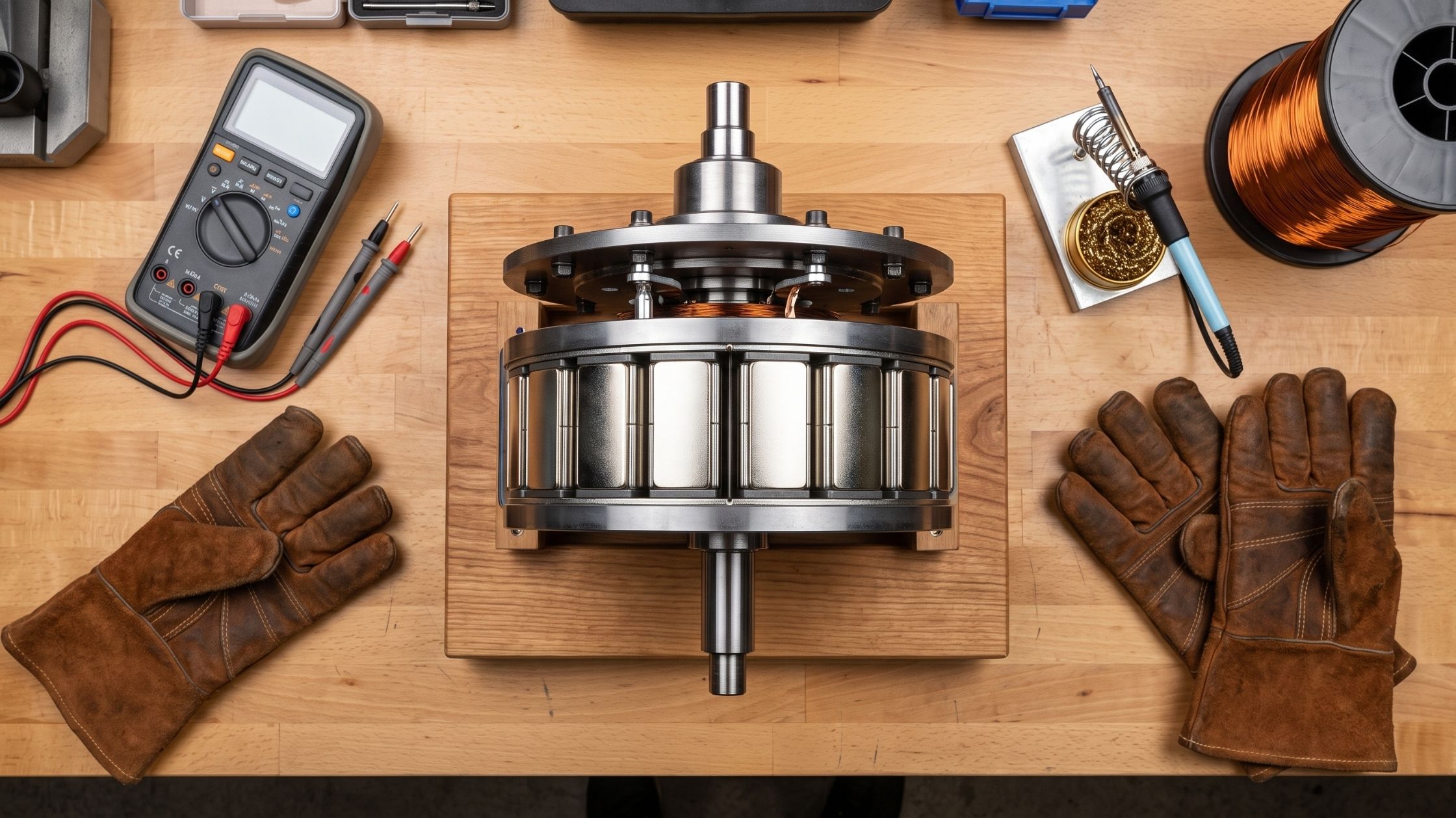
Building a neodymium magnet generator requires absolute precision. The quality of your components will directly dictate your maximum power output and the unit’s longevity. Below is the master list of materials and tools I use to fabricate a standard 1,000-watt (1kW) axial flux generator.
Core Materials
- Neodymium Magnets: You will need 24 pieces of N52 grade neodymium magnets, typically sized at 2″ x 1″ x 0.5″ block magnets. The “N52” designation refers to the magnet’s maximum energy product. It is the strongest grade available to consumers and is completely non-negotiable for a high-yield generator.
- Magnet Wire: Source 3 to 5 pounds of AWG 14 enameled copper wire. Do not use standard plastic-insulated household wire. Magnet wire has a microscopically thin enamel coating. As a result, you can pack the windings tightly together, which drastically increases electrical output.
- Steel Disks for Rotors: Use two 1/4-inch thick mild steel disks, approximately 12 inches in diameter. Steel is specifically required because it completes the magnetic circuit and directs the flux through the coils. Never use aluminum, wood, or stainless steel for your rotor plates. These materials are non-magnetic and will ruin the machine’s efficiency.
- Stator Casting Resin: You will need a high-temperature polyester or two-part epoxy resin, combined with woven fiberglass cloth. This mixture is used to cast the copper coils into a solid, rigid stator disc.
- Bearing and Shaft Assembly: A heavy-duty automotive or trailer wheel hub assembly works perfectly for the mechanical spin axis. It is already engineered to handle high rotational speeds, lateral forces, and significant weight.
- Electrical Components: Source a heavy-duty 3-phase bridge rectifier rated for at least 50 amps and 1,000 volts. You will also need smoothing capacitors and AWG 10 stranded copper wire for power transmission from the generator to your battery bank.
Essential Tools
- Digital Multimeter: Essential for measuring voltage, resistance (ohms), and checking for short circuits.
- Soldering Iron: Use a high-wattage (at least 60W) soldering station with rosin-core electrical solder for securing wire connections.
- Coil Winder: You can build a simple DIY winding jig out of scrap wood, a long bolt, and a hand crank. This ensures your copper coils are uniform.
- Precision Measuring Tools: A digital caliper is mandatory for measuring the air gap between the rotors and the stator.
- Safety Gear: Heavy leather work gloves, wrap-around safety glasses, and a respirator mask to protect against epoxy fumes and metal dust.
Note: Sourcing quality components is critical. I strongly recommend purchasing your N52 magnets and enameled copper wire from reputable industrial suppliers. Cheap online marketplaces are flooded with counterfeit, low-strength magnets that will severely limit your generator’s output.
Ready to Build Your Own Off-Grid Power System?
The number one reason DIY magnetic generators fail isn’t the physics—it is a lack of precision tools. Don’t drill a single hole or twist a single wire until your workspace is set up like a professional energy lab. Grab our free 17-page blueprint covering the exact tools, safety gear, and air-gap instruments you need to succeed on your first try. (PDF format, No email needed)
Step-by-Step Construction Guide
Building a permanent magnetic generator requires patience and a methodical approach. Rushing the assembly will lead to short circuits or catastrophic mechanical failure. In this section, we will build a 3-phase axial flux generator.
Phase 1: Winding the Copper Coils
The copper coil assembly is the heart of your generator. For a standard 3-phase, 9-coil, 12-magnet design, you will need to wind 9 identical coils.
- Build a simple wooden coil winding jig that matches the exact geometric shape of your magnets. This is usually a trapezoid or rectangle, but slightly larger than the magnet itself.
- Wind exactly 70 turns of AWG 14 enameled copper wire for each coil. Keep the windings as tight, flat, and uniform as possible. Loose windings take up more physical space, which forces a wider air gap and kills efficiency.
- Leave about 6 to 8 inches of loose wire on both the starting and ending leads of each coil.
- Wrap the finished coils lightly in electrical tape to hold their shape. Then, use your multimeter to measure the resistance of each coil. They should all produce identical ohm readings. If one coil reads drastically lower, it has a short and must be rewound.
Phase 2: Casting the Stator
The stator holds the copper coils entirely stationary while the powerful magnets spin around them.
- Create a circular casting mold from melamine wood or a high-density non-stick plastic cutting board.
- Arrange your 9 coils in a perfect circle inside the mold.
- Connect the coils in a 3-phase configuration. You can wire them in “Star” (higher voltage at low RPMs) or “Delta” (higher current). For variable sources like wind, I strongly recommend the Star configuration.
- Scrape the enamel off the wire ends to expose bare copper. Next, solder the connections firmly and route your three main AC output leads out of the mold.
- Mix your high-temperature epoxy resin carefully. Pour a thin layer into the mold, then lay down a sheet of fiberglass mesh for structural rigidity. Place the coils and pour the remaining resin to encapsulate them fully. Ensure there are no air bubbles.
- Let the stator cure for 24 to 48 hours at room temperature before removing it from the mold.
Phase 3: Assembling the Magnetic Rotors
WARNING: Neodymium magnets of this size are incredibly dangerous. They can crush fingers, pinch skin, and shatter into sharp shrapnel if allowed to snap together. Wear heavy leather gloves and use extreme caution.
- Take your two 12-inch steel disks. Using a protractor, mark out 12 perfectly spaced mounting positions (every 30 degrees) on each disk.
- Mount the magnets to the steel disks at the marked intervals using a strong cyanoacrylate adhesive, followed by a two-part epoxy.
- Critical Step: Alternate the magnetic poles—North, South, North, South—all the way around the disk. Use a small compass to verify the polarity of each magnet face.
- When assembling the second disk, the magnets must face the opposite polarity of the bottom disk. For example, a North pole on the top disk must directly face a South pole on the bottom disk. This arrangement creates a direct magnetic flux field that shoots straight through your cast copper stator.
- Pour a thin layer of epoxy resin over and between the mounted magnets to secure them permanently. This prevents them from flying off due to centrifugal force at high RPMs.
Phase 4: Final Mechanical Assembly
- Mount your heavy-duty trailer hub vertically on a sturdy steel or wooden test bench frame.
- Attach the bottom magnetic rotor disk to the spinning hub plate.
- Mount the cast stator directly above the bottom rotor. The stator must be fixed solidly to the stationary frame—it does not spin. Adjust the mounting bolts so there is a gap of exactly 1/16th of an inch between the spinning magnets and the stationary stator.
- Carefully lower the top rotor disk onto the hub. The magnetic attraction to the bottom plate will be extremely strong. Therefore, use long threaded rods and nuts to slowly lower the top disk into place until you achieve another 1/16th-inch gap above the stator.
- The Golden Rule: A tighter air gap between the magnets and the stator produces more power. However, if the gap is too tight, the rotors will scrape the stator. Precision is everything here.
Wiring and Electrical Safety
Working with a permanent magnetic generator is not a harmless science experiment. Even a modestly sized DIY unit can produce lethal voltages—well over 150V AC—if spun at high speeds without a battery load connected.
CRITICAL ELECTRICAL SAFETY DISCLAIMER: Electrical generation systems pose severe shock and fire hazards. Always comply with the National Electrical Code (NEC) and your local municipal building codes. Ensure your metal generator frame and tower are properly grounded to an earth grounding rod. This mitigates lightning strikes and static buildup. Never touch the bare AC output leads while the rotors are spinning.
The three AC output wires from your stator must be routed to your 3-phase bridge rectifier. This electronic component acts as a series of one-way valves. Specifically, it flips the negative AC sine waves into positive DC power.
- Crimp heavy-duty copper ring terminals onto the three stator leads and bolt them to the AC input terminals of the rectifier.
- Next, route the DC output terminals—Positive and Negative—via heavy-gauge wire to your renewable energy charge controller.
- Never connect a raw generator directly to a battery without a charge controller and a dump load. When your battery bank is full, the turbine has nowhere to send the electrical energy. The charge controller senses this and diverts excess energy to a dump load, such as a resistive water heating element. Without a dump load, the generator loses its electromagnetic braking force, freewheels, and suffers catastrophic mechanical destruction.
Testing and Troubleshooting Your Generator
Open-Circuit Voltage Test
Before installing your generator on a tower or connecting it to a battery bank, you must bench-test it rigorously. Attach your digital multimeter to the DC output terminals of the rectifier. Then, spin the rotor by hand or with a variable-speed power drill at a known RPM. A well-built axial flux generator should produce around 12 to 14 volts at just 100 to 120 RPM. This low-RPM output is ideal for charging a 12V battery system in low-wind conditions.
Short-Circuit Test
With the generator stationary, connect an ammeter across the positive and negative leads. Give the rotor a manual spin. You will immediately notice that the generator physically resists spinning—it will feel like turning a paddle through thick mud. This is known as EMF braking, or Lenz’s Law in action. It confirms that your magnetic fields are dense and your coils are correctly wired without shorts.
Common Troubleshooting Issues
- Low Voltage Output: Check your air gap with a caliper. If the gap between the magnets and the stator is too wide, the magnetic flux drops exponentially. Consequently, you should carefully tighten the mechanical clearances to the recommended 1/16th of an inch.
- Stator Melting or Overheating: This is caused by excessive resistive heating, known as I²R losses. Your wire gauge might be too thin for the current you are drawing. Alternatively, your system may be pushing too much power into a heavily depleted battery.
- Loud Grinding Noises: The rotor is making physical contact with the stator. Stop spinning the generator immediately. Then, adjust the mechanical clearances on your threaded rods to prevent stator damage.
Maintenance Best Practices
To ensure your permanent magnetic generator lasts for decades, routine preventative maintenance is non-negotiable. Although these DIY generators have no carbon brushes to wear out, they are highly susceptible to environmental degradation—especially when mounted outdoors.
- Corrosion Checks: Neodymium magnets rust and flake away quickly when exposed to moisture. Ensure the epoxy resin coating on your rotors remains fully intact. If you notice chips or exposed metal, lightly sand and re-coat the area immediately with a marine-grade polyurethane or epoxy.
- Bearing Lubrication: The wheel hub bearings carry the entire mechanical load, vibrational stress, and gyroscopic forces of the generator. Therefore, disassemble and pack them with high-temperature automotive lithium grease at least twice a year.
- UV Protection: Direct sunlight causes epoxy to degrade, turning yellow and brittle over time. As a result, paint the outside edges of the stator with an opaque, UV-resistant outdoor enamel.
- Wiring Inspections: Wind, vibration, and thermal expansion will loosen electrical connections over time. Check all crimps, mounting lugs, and rectifier terminals every three months to prevent electrical arcing, which can start a fire.
Design Optimization and Power Output
When beginners search for a “free energy generator,” they often hold unrealistic expectations of unlimited power. In reality, output is strictly constrained by the mechanical energy fed into the system and the electromechanical efficiency of the generator itself.
A well-optimized permanent magnetic generator can achieve up to 80–85% efficiency. Here is how experts maximize output:
- Strict Magnet Selection: Never substitute cheaper samarium-cobalt or ceramic ferrite magnets. Although they cost far less, their magnetic flux density is significantly weaker than N52 neodymium magnets. Weak magnets directly produce weak power output.
- Minimizing Eddy Currents: If you use solid steel cores inside your copper coils to boost flux, the steel must be laminated into ultra-thin sheets. Otherwise, parasitic eddy currents will generate intense heat and melt your stator. This is precisely why air-core stators—encapsulated entirely in resin—are the gold standard for DIYers.
- Realistic Power Output: An 18-inch diameter generator built with 2-inch neodymium magnets and AWG 12 wire can comfortably output 1kW to 3kW, depending on RPM. Scaling up to 24-inch rotors with double-stacked magnet arrays can push output beyond 10kW. However, designs at that scale require serious structural engineering and are strictly not for beginners.
Is a Permanent Magnetic Generator Right for Your Home?
Who Should Build One
Building a home magnetic generator is an empowering gateway to true energy independence. Nevertheless, it is not the right fit for every household. If you live in a dense suburban neighborhood with strict HOA rules, a 20-foot wind turbine may not be legally feasible. On the other hand, if you live in a rural or off-grid area, have access to a continuously flowing stream, or experience consistent wind speeds averaging above 10 mph, a DIY permanent magnetic generator is highly practical and cost-effective.
Cost-Benefit Considerations
Commercial wind turbines or micro-hydro generators can cost upwards of $3,000 to $10,000. By contrast, sourcing your own rare-earth magnets, copper wire, and scrap steel allows you to build a comparable, rugged generator for under $500.
Furthermore, this approach provides emissions-free, localized energy production. The scalability is entirely in your hands. You can start with a small 500W model to charge 12V lighting batteries, then eventually scale up to a 5kW system capable of running major appliances, water pumps, and refrigerators. For eco-conscious DIYers and preppers alike, mastering this technology is the ultimate weekend project.
FAQ Section
What is the difference between a permanent magnetic generator and a standard car alternator?
A standard automotive alternator requires an electromagnet—the field coil—to create its initial magnetic field. Consequently, it consumes a portion of the electricity it generates just to sustain itself. It also needs high RPMs to work effectively. By contrast, a permanent magnetic generator uses static rare-earth magnets. As a result, 100% of the mechanical energy converts directly to electricity without parasitic losses, and it performs efficiently at very low RPMs.
Can a permanent magnetic generator power my entire house?
Yes, but it requires a significantly large system. To power an average modern home, you would need a generator in the 10kW to 15kW range, a large mechanical energy source, and a substantial battery bank and inverter system. In practice, most DIY magnetic generators are used to supplement grid power, charge RVs, or run specific off-grid circuits like well pumps and lighting.
How do you prevent a permanent magnetic generator from overheating under load?
Overheating is prevented through careful design. First, use the correct thick-gauge copper wire, since lower AWG numbers mean thicker wire that handles more current without heating. Second, ensure proper airflow over the stator. Third, use a high-quality diversion charge controller. The controller redirects excess current to a dump load, preventing the stator from exceeding its maximum rated amperage.
Is a neodymium magnet generator truly a “free energy generator”?
No, and you should be wary of any source claiming otherwise. In the renewable energy community, “free energy” strictly refers to the source of mechanical power—wind or flowing water—which carries no monthly utility cost. The generator itself strictly obeys the laws of thermodynamics. In other words, it is physically impossible to extract more electrical energy from the machine than the mechanical energy you put into spinning the rotor.
How do I choose the right copper wire size for my home magnetic generator?
Wire gauge determines your generator’s voltage and current profile. Thinner wire (e.g., AWG 18) lets you pack more turns into each coil, which produces higher voltage at low rotational speeds. This is ideal for low-wind areas. Conversely, thicker wire (e.g., AWG 12) limits the number of turns, so you need higher RPMs to reach your target voltage. However, it handles much higher current without melting. As a result, thick wire works best for high-torque hydro applications where rotational speed is fast and constant.
Conclusion
Building your own permanent magnetic generator is one of the most mechanically rewarding projects a DIYer can undertake. By directly harnessing the physics of electromagnetism through carefully wound copper coils and powerful rare-earth magnets, you can create a robust electrical system capable of generating off-grid power for decades.
Whether you want to build a backyard wind turbine to cut utility bills, construct a micro-hydro system for a remote cabin, or simply understand the fundamentals of electrical engineering, this guide provides the exact roadmap you need. Always source high-quality components, measure your air gaps precisely for maximum efficiency, and above all else, prioritize electrical and mechanical safety at every step.
Author Bio: As a certified renewable energy technician and dedicated off-grid homesteader, I have spent over a decade designing, building, and troubleshooting custom solar, wind, and micro-hydro power systems. With a formal background in electrical systems and sustainable engineering, I specialize in cutting through the jargon to translate complex electromechanical concepts into actionable, safe, and highly efficient DIY projects for the modern eco-conscious builder. When I’m not in the workshop winding stators, I’m consulting on rural energy independence.