Unlike grid-tied systems where utility power acts as an automatic backup, an off-grid solar installation requires active oversight. In an off-grid configuration, a single degraded battery cell, a tripped ground-fault interrupter, or undetected panel soiling directly compromises your power availability.
Maintaining an off-grid system does not require daily manual labor, but it does demand a structured inspection schedule, disciplined performance logging, and clear diagnostic protocols.
This guide details ongoing maintenance schedules, cost models, performance optimization techniques, and systematic troubleshooting procedures for off-grid photovoltaic (PV) systems.
⚠️ ELECTRICAL SAFETY WARNING:
Off-Grid photovoltaic arrays operate at lethal DC voltages (150V – 600V) with high fault currents. Unlike AC power, DC arcs do not self-extinguish at zero-crossings. Always use insulated hand tools rated for 1,000V, remove metallic jewelry, wear safety glasses and class-0 electrical gloves, and turn off all DC and AC isolation switches before servicing live wiring.
1. The True Cost of Maintaining an Off-Grid Solar System
While solar fuel is free, maintaining electrical balance, mechanical hardware, and electrochemical storage requires planned budgeting.
Lifecycle Expense & Replacement Timetable
| Component / Task | Expected Lifespan | Typical Replacement / Maintenance Cost | Maintenance Frequency |
|---|---|---|---|
| Solar PV Panels | 25–30 Years | $0 (Covered by 25-year performance warranties) | Visual check: 2x/year; Cleaning: 2–4x/year |
| LiFePO_4 Battery Bank | 10–15 Years | $3,500 – $10,000 (Full replacement) | Automated internal balancing; Monthly terminal check |
| Lead-Acid / AGM Bank | 3–6 Years | $2,000 – $6,000 (Full replacement) | Monthly specific gravity checks; Equalization every 30–90 days |
| Off-Grid Inverter / Charger | 8–12 Years | $1,200 – $3,500 (Unit replacement / capacitor rebuild) | Annual fan filter cleaning and firmware audits |
| MPPT Charge Controller | 10–15 Years | $350 – $1,200 (Unit replacement) | Annual dust clearing and terminal torque check |
| Auxiliary Generator | 2,000–5,000 Hours | $150 – $300/year (Oil, filters, spark plugs) | Oil change every 100–250 run hours |
| Balance of System (BOS) | 20+ Years | $100 – $400 (Fuses, surge arrestors, breakers) | Annual thermal scan & re-torquing |
Budgeting Rule of Thumb
Budget 1.5% to 2.5% of the initial total system capital cost per year into a dedicated reserve fund. For a standard $15,000 DIY system, saving $250 to $375 annually ensures cash reserves are available when an inverter reaches the end of its design life or generator components require servicing.
2. Maintenance Schedules: Daily to Annual Protocols
Systematic maintenance avoids unexpected equipment breakdowns. Follow this chronological schedule to keep all components operating within manufacturer specifications.
- Daily ──► Inverter/BMS Dashboard Status, State of Charge (SoC), Error Codes
- Monthly ──► Array Soiling Check, Battery Terminal Torques, Air Filter Cleaning
- Quarterly ──► Solar Array Deep Cleaning, Seasonal Tilt Adjustments, Generator Run
- Annual ──► Thermal Imaging (FLIR), Wire Re-Torque, Full Safety Disconnect Test
Daily & Weekly Check-Ins (1 Minute)
- Verify State of Charge (SoC): Confirm that your battery bank hits 100% float saturation at least 2 to 3 times per week.
- Review Inverter/BMS Display: Check for warning indicators, grounding alerts, or irregular temperature readings.
- Monitor Auxiliary Fuel & Generator Status: Check generator fuel levels, coolant, and auto-start readiness if an auxiliary unit is integrated.
Monthly Maintenance (30 Minutes)
- Inverter & Controller Air Vents: Vacuum dust and debris from cooling intake fans and exhaust ports. Blocked airflow increases internal thermal stress on electrolytic capacitors.
- Flooded Lead-Acid Servicing (If Applicable):
- Check electrolyte fluid levels across every individual cell.
- Top up exclusively with distilled deionized water (never tap or mineral water).
- Measure specific gravity using a temperature-compensating hydrometer (standard reading: 1.265 – 1.280 at 25°C).
- Lithium (LiFePO_4) Cell Voltage Delta: Check your Battery Management System (BMS) app or monitor screen. The voltage delta between the highest and lowest cell should stay below 0.020V – 0.035V in a fully rested state.
Quarterly & Seasonal Tasks (1–2 Hours)
- Array Soiling & Debris Clearing: Clear fallen leaves, bird droppings, moss, pollen, and airborne dust layers from panel glass surfaces.
- Adjust Seasonal Tilt Angles (If using adjustable mounts):
- Summer Tilt: Latitude – 15°C (Optimizes high-angle overhead midday sun).
- Winter Tilt: Latitude + 15°C (Optimizes low-angle sun rays and sheds snow automatically).
- Spring / Fall: Set to your geographical latitude.
- Exercise the Auxiliary Generator: Run your backup generator under electrical load for at least 30 minutes to lubricate engine components and prevent fuel stabilizer breakdown.
Annual Engineering Audit (Half Day)
- Mechanical Mounting Inspection: Inspect all roof mounting brackets, L-feet, torque clamps, and ground-mount foundation bolts for structural integrity and corrosion.
- Electrical Terminal Re-Torquing: Use an insulated, calibrated torque wrench to re-torque all battery studs, combiner box terminals, and breaker connections to the manufacturer’s specified inch-pounds (in-lbs or N . m). Vibration and thermal expansion loosen screw connections over time, introducing high electrical resistance.
- Infrared Thermal Scan: Use a handheld thermal camera (FLIR) while the system is operating under heavy midday load. Look for hot spots (>60°C) on:
- Solar panel cells (indicating bypass diode failure or internal microcracks).
- DC disconnect switches and breakers.
- Battery busbar link connections.
3. Common Issues That Degrade Off-Grid Performance
When an off-grid system underperforms, the issue usually traces back to one of several core failure modes:
| Issue | Operational Consequence |
| 1. Array Soiling & Micro-Shade | Slices total string current via series current limiting |
| 2. Lead-Acid Sulfation | Permanent loss of usable amp-hour capacity |
| 3. Lithium BMS Trip | Sudden shutdown of battery output under moderate load |
| 4. Ground Faults (GFDI) | Inverter stops converting power to protect human life |
| 5. Thermal Derating | Reduced energy production during peak summer days |
1. Panel Soiling, Shading, and Bypass Diode Activation
Solar cells wired in series act like a pipe system. If a single cell in a 72-cell panel is blocked by dirt or heavy shading, it acts as a resistor rather than a generator.
- Current must pass through internal bypass diodes.
- Continuous diode conduction generates localized heat, reducing string voltage and potentially causing hot spot burns that permanently discolor the module glass.
2. Battery Bank Stratification and Sulfation
- Sulfation (Lead-Acid): Occurs when batteries sit below an 80% charge state for extended periods. Lead sulfate converts into hard crystalline forms on the lead plates, permanently reducing capacity.
- Cell Imbalance (LiFePO}_4): Lithium cells charge and discharge at slightly different efficiencies. Without regular saturation to allow the internal BMS to balance individual cell voltages, one “low” cell will trigger an under-voltage cutoff early, causing the entire battery bank to shut down prematurely.
3. Thermal Inverter & Controller Derating
Power electronics lose conversion efficiency as temperature rises. When ambient utility room temperatures exceed 40°C (104 degrees F), inverters throttle their continuous wattage output to prevent internal silicon damage.
4. Step-by-Step Diagnostic & Troubleshooting Procedures
When your off-grid system triggers an error code or fails to provide power, follow this structured diagnostic protocol to isolate the root cause safely.
[ Problem Occurs: Power Loss / Warning Code ]
                     │
                     ▼
[ Check Central Inverter & Charge Controller Display ]
                     │
        ┌────────────┴────────────┐
        ▼                         ▼
 [ DC Array Side Fault ]    [ Battery Storage Fault ]
        │                         │
  - Measure String Voc      - Check Total Resting Voltage
  - Test Short Circuit Isc  - Inspect BMS Communication Link
  - Inspect Combiner Fuses  - Measure Per-Cell Voltage Delta
Diagnostic Procedure A: Troubleshooting the Solar Array
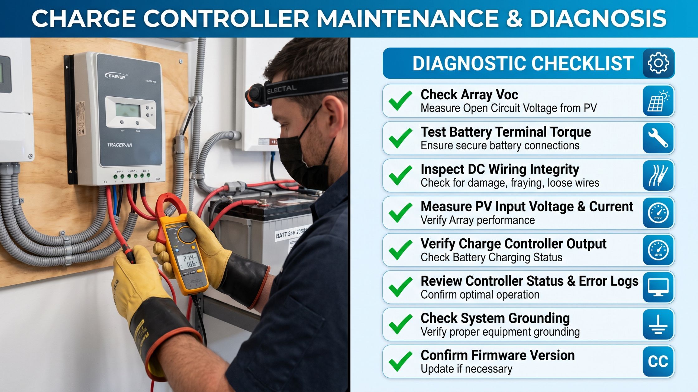
Step 1: Measure Open-Circuit Voltage (V_oc)
- Isolate the solar array by opening the main DC disconnect switch.
- Set your digital multimeter to DC Volts (1,000V range).
- Measure the voltage across the positive (+) and negative (-) terminals of each string in your combiner box.
- Compare your reading against the theoretical cold-adjusted string voltage:
V_oc = Panels in Series x V_oc (STC) x [1 + Temp Coeff x (T_ambient – 25°C)]
- Normal: The reading is within 5% to 10% of calculated V_oc.
- Low Voltage: If voltage is lower by roughly 35V – 45V (the voltage of one panel), one panel in the string has a blown bypass diode, a disconnected MC4 connector, or heavy localized shading.
- Zero Volts: Check for an open string fuse, broken conductor, or trip in the DC surge protection device.
Step 2: Measure Short-Circuit Current (I_sc)
- Keep the string isolated.
- Use a calibrated DC Clamp Meter clamped around the positive conductor of the string.
- Briefly close a fused DC disconnect switch or measure operating current (I_mp) under full sun.
- The reading should be within 10% of the module’s rated I_sc listed on the backplate tag, scaled down proportionally to the cloud cover index.
Diagnostic Procedure B: Troubleshooting the Battery Storage
Step 1: Measure Total Resting Bank Voltage
Rest the battery bank by disconnecting incoming solar charging and shutting off downstream inverter loads for at least 30 minutes.
| Battery Chemistry | 100% Full SoC (Resting) | 50% SoC (Warning Level) | 0% – 10% SoC (Critical Low) |
|---|---|---|---|
| 12V Lead-Acid / AGM | 12.70V – 12.85V | 12.20V | 10.50V – 11.80V |
| 24V Lead-Acid / AGM | 25.40V – 25.70V | 24.40V | 21.00V – 23.60V |
| 48V Lead-Acid / AGM | 50.80V – 51.40V | 48.80V | 42.00V – 47.20V |
| 48V Lithium (LiFePO_4) | 53.60V – 54.40V | 52.40V – 52.80V | 48.00V – 50.00V |
- If Lithium Bank Voltage is <42V on a 48V System: The internal BMS has tripped its low-voltage disconnect protection. Modern inverters cannot detect a voltage reference on their terminals and will refuse to charge. You must connect an external lithium-activation charger or use an auxiliary generator in manual override mode to wake up the BMS.
Step 2: Check for High-Resistance Interconnects
- Put the battery bank under a heavy inverter load (such as a 1,500W kettle or well pump).
- Set your multimeter to Millivolts (mV DC).
- Place one probe on the battery post and the other probe directly on the crimped terminal lug attached to that post.
- Analysis: A reading above 15mV – 25mV indicates a high-resistance joint caused by corrosion, insufficient torque, or inadequate wire gauge. Clean the mating surfaces with a wire brush, apply dielectric grease, and re-torque.
Diagnostic Procedure C: Inverter & Electrical Fault Decoding
| Fault Code Symptom | Root Cause & Corrective Action |
| Low DC Input Voltage | Battery depleted, high cable voltage drop, or loose lug |
| High DC Input Voltage | Charge controller overshooting absorption limit |
| Over-Temperature Fault | Clogged fan filters, ambient room temp >45°C |
| Ground Fault Warning | Moisture in roof junction box or damaged wire insulation |
| AC Overload / Surge Error | Inductive motor start draw exceeding peak surge limit |
Fixing Ground-Fault Errors (GFDI)
A ground-fault trip occurs when current escapes the intended circuit conductors and flows through the equipment grounding system.
- Open the main DC input breaker from the solar array.
- Turn off the inverter and charge controller.
- Set your multimeter to Megohms (MΩ) Resistance.
- Test between the Positive DC conductor and Ground, then between the Negative DC conductor and Ground.
- Expected Reading: Resistance should read Open Loop / Infinite (∞Ω).
- If the resistance measures below 1MΩ, check exterior rooftop combiner boxes for water intrusion, cracked wire conduits, or conductors abraded against aluminum racking edges.
5. Boosting Efficiency: Squeezing Maximum kWh From Your System
If your system is operating without errors but daily generation feels low, use these electrical and physical adjustments to boost performance.
1. Optimize MPPT Voltage Headroom
MPPT charge controllers require an array voltage at least 5V to 10V higher than the battery bank’s absorption voltage to begin conversion.
- Wiring panels in long series strings (e.g., 150V – 350V DC) keeps the controller operating at its highest efficiency point (97% – 99%) even during low-light morning, evening, and overcast conditions.
2. Mitigate Thermal Losses via Air Gap Engineering
Photovoltaic panel output drops by roughly 0.30% to 0.38% for every degree Celsius above 25°C panel temperature.
- Roof-mounted panels flush-mounted without adequate clearance can reach temperatures of 70°C (158°F), losing nearly 17% of their rated peak output.
- Solution: Maintain at least a 10cm – 15cm (4 – 6 inches) open air gap between the roof deck and the underside of the panel frames to promote passive convective cooling.
       Sunlight
          │││
          ▼▼▼
┌───────────────────────┐  ◄── Solar Panel Module
└───────────────────────┘
  ═════════════════════    ◄── Free Airflow Boundary Layer (10cm - 15cm Gap)
─────────────────────────  ◄── Metal / Tile Roof Surface
3. Minimize Cable Voltage Drop
Size all low-voltage DC cable runs so that total voltage drop from the array to the battery, and the battery to the inverter, is under 2%.
Voltage Drop (V) = 2 x Length (ft) x Current (Amps) x Resistance per 1000ft / 1000
Upgrading an undersized battery interconnect from 2 AWG to 4/0 AWG (0000 AWG) can prevent hundreds of watts of power loss dissipated as waste heat during high inverter draws.
4. Smart Load Shifting (The Zero-Cost Efficiency Boost)
The most efficient way to use solar power is consuming it directly as it is generated, bypassing the battery round-trip efficiency penalty (10% – 20% energy loss during chemical storage and retrieval).
- Schedule energy-intensive appliances (well pumps, clothes washers, water heaters, power tool charging) between 10:00 AM and 2:30 PM.
- By running loads during peak absorption times, you use solar power at direct 97% conversion efficiency while reducing battery thermal cycles.
6. Seasonal Readiness Checklist
Adjust maintenance habits based on the time of year to prevent environmental damage:
Winter / Rainy Season Checklist
- [ ] Adjust array tilt to maximum steep angle to catch low-horizon sun and shed snow/rain.
- [ ] Verify battery temperature compensation sensor is securely attached to lead-acid banks (cold batteries require higher charging voltages).
- [ ] Ensure lithium batteries are kept above 0°C (32°F); never charge LiFePO_4 cells below freezing, as doing so causes irreversible lithium metal plating.
- [ ] Check auxiliary generator block heaters, fuel additives, and auto-start signal lines.
Summer / Dry Season Checklist
- [ ] Wash dust and pollen coatings from panels using cool water early in the morning before solar glass heats up (cold water on hot glass can cause thermal fracture).
- [ ] Check inverter utility room ventilation fans and clear louvers of insects or dirt.
- [ ] Inspect flooded lead-acid electrolyte levels weekly during extended periods of heat.
- [ ] Verify surge protective devices (SPD) are functional ahead of seasonal lightning storms.
By adhering to these systematic maintenance protocols, verifying terminal torques, and understanding basic multimeter diagnostic steps, your off-grid system will deliver reliable energy year after year.
To see a technician’s multimeter testing workflow in action, watch this How to troubleshoot solar panel string voltage and current walkthrough. It demonstrates how to safely isolate strings, measure open-circuit voltage (V_oc), and test current outputs with a clamp meter.