Installing your own residential solar power system is one of the highest-yield DIY home-improvement projects you can undertake. By taking on the labor yourself, you can eliminate contractor markups, cut total installation costs by 40% to 60%, and gain complete technical understanding of your home’s power generation.
However, a grid-tied or off-grid solar photovoltaic (PV) installation is not a casual weekend craft project. It requires structural roofing work, adherence to the National Electrical Code (NEC), high-voltage DC safety precautions, and precise electrical commissioning.
This comprehensive master guide walks you step-by-step through evaluating installation difficulty, acquiring the exact required tools, mounting structural hardware, wiring DC strings, bonding system grounding, and safely commissioning your array.
1. Reality Check: How Hard Is It to Install Solar Panels Yourself?
Before purchasing thousands of dollars in hardware, you must honestly evaluate the two distinct skill sets required for a safe installation: Mechanical/Structural Carpentry and Electrical Engineering.
DIY SOLAR INSTALLATION SKILL MATRIX
| Mechanical / Structural Difficulty: Moderate | – Comfortable working at roof heights / pitch – Finding rafters beneath skip sheathing – Flashing & weatherproofing roof decks – Aligning heavy aluminum rails & torquing |
| Electrical / Wiring Difficulty: High | – Understanding DC series vs. parallel strings – Calculating cold-weather voltage spikes (Voc) – Crimping MC4 connectors & pulling conduit – Grounding, bonding, and main panel tying |
Physical Demands vs. Technical Demands
- The Physical Challenge: Standard residential solar panels measure roughly 68 x 40 inches (or larger for 450W+ commercial modules) and weigh 40 to 55 lbs each. Hoisting 12 to 24 of these large glass-and-aluminum sails up a ladder and securing them across an angled, sun-baked roof requires physical stamina and strict fall-protection discipline.
- The Technical Challenge: While mounting rails is straightforward carpentry, electrical wiring demands zero margin for error. A loose DC connection can generate an electric arc reaching thousands of degrees Celsius, which does not self-extinguish like AC current.
Financial Comparison: DIY vs. Turnkey Professional Installation
| Cost Factor | Professional Turnkey Install (8kW System) | DIY Self-Installation (8kW System) |
|---|---|---|
| Gross Hardware Cost (Panels, Inverter, Racking, BOS) | $8,000 – $10,500 | $6,500 – $8,500 (Direct wholesale / pallet buy) |
| Labor & Contractor Overhead | $8,000 – $12,000 | $0 (Self-installed labor) |
| Permitting, Engineering Plans & Interconnection | Included in contract | $300 – $800 (Online drafting & local fees) |
| Total Upfront Out-of-Pocket | $18,000 – $24,000 | $7,000 – $9,500 |
| Average Cost per Watt (DC) | $2.25 – $3.00 / Watt | $0.85 – $1.20 / Watt |
2. Required Tools & Safety Equipment
Having the correct, specialized tools before starting is the difference between a clean, leak-free, code-compliant install and ruined equipment or personal injury. Do not substitute general household tools for specialized electrical crimpers and insulated equipment.
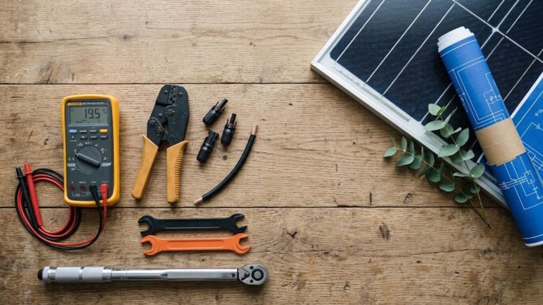
REQUIRED TOOLS CHECKLIST
| Electrical & Diagnostic Tools – CAT III/IV 1000V Multimeter – Dedicated MC4 Crimping Tool – Heavy-Duty Cable Cutters/Stripper – EMT Conduit Bender (1/2″ & 3/4″) – Fish Tape / Wire Pulling Lube | Mechanical & Carpentry Tools – Impact Driver & Cordless Drill – Calibrated Torque Wrench – Chalk Line & Magnetic Torpedo Level – Deep Well Sockets (1/2″, 9/16″) – Rafter Finder / Rubber Mallet |
| Safety Gear & PPE – OSHA Full-Body Fall Arrest Kit – 1000V Insulated Hand Tools – Class 0 Insulated Gloves (1000V) – UV Safety Glasses & Grip Gloves | Weatherproofing & Sundries – Polyurethane Roof Sealant – Stainless Cable Clips / Zip Ties – Flashing Plates & Lag Hardware – Conduit Bushings & Grounding Lugs |
Specialized Electrical Tools
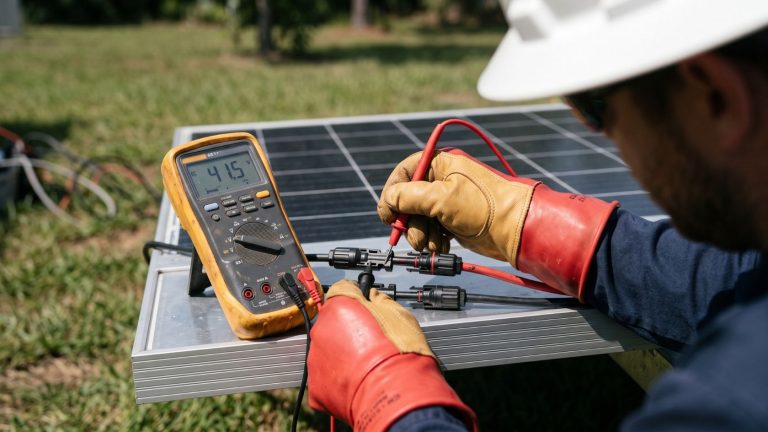
- True-RMS Digital Multimeter with CAT III 1,000V / CAT IV 600V Rating: Essential for verifying string open-circuit voltage (Voc), operating current (Isc), and ground continuity.
- Specialized MC4 Ratcheting Crimper & Disconnect Spanners: Standard wire crimpers will crush MC4 solar pins unevenly, creating high-resistance hot spots. A dedicated ratcheting tool ensures a gas-tight, factory-grade crimp on 10 AWG and 12 AWG solar PV wire.
- EMT Conduit Bender (1/2 in. and 3/4 in.): For running clean, protective metal conduit from the roof penetrations down to your disconnect switch and inverter.
- Fish Tape (50 ft.) & Pulling Lubricant: Required for pulling stiff, heavy-gauge THHN wire strings through long conduit runs and tight 90° sweeps.
Specialized Structural & Carpentry Tools
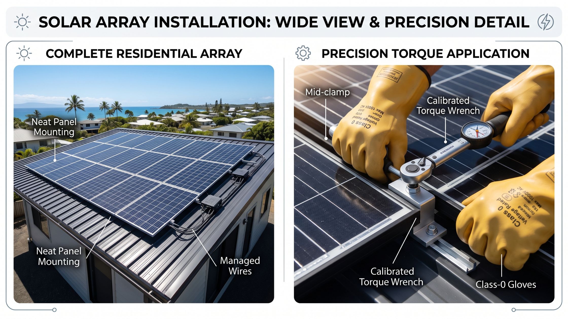
- Calibrated Click-Type Torque Wrench (in-lbs and ft-lbs): Solar mounting brackets, mid-clamps, and ground lugs have strict manufacturer torque specifications (usually 85 to 140 in-lbs). Under-torquing leads to panels lifting in high winds; over-torquing cracks the module glass frame.
- Stud / Rafter Locator & Non-Marring Rubber Mallet: Used for locating structural framing members through shingles and roof sheathing.
- Chalk Line & Long Magnetic Level: For striking straight, parallel reference lines across roof planes to prevent rail misalignment.
- Deep-Socket Impact Set: For driving heavy 5/16 in. or 3/8 in. structural lag bolts into rafters.
Safety Gear (Non-Negotiable PPE)
- OSHA-Compliant Fall Protection Harness Kit: Includes a full-body harness, shock-absorbing lanyard, roof ridge anchor bracket, and a 50 ft. vertical lifeline with a mechanical rope grab.
- 1,000V Rated Insulated Hand Tool Set: Screwdrivers, diagonal cutters, and pliers insulated to prevent accidental arc flashes when working inside combiner boxes and disconnect enclosures.
- Roofing Footwear: Flexible, high-traction, soft-rubber-soled work boots to prevent slipping on composite shingles or metal sheets.
Roofing Sealants & Sundries
- High-Grade Polyurethane Roof Sealant (e.g., M-1, ChemLink, or Geocel 4500): Never use cheap silicone caulk. You need structural, elastomeric polyurethanes that maintain elasticity across extreme thermal freeze-and-bake cycles.
- Stainless Steel Cable Clips: For securing DC PV wire along the underside of rail channels to prevent sagging onto abrasive roof surfaces.
3. Pre-Installation Planning, Permitting & Site Assessment
A successful installation begins long before stepping onto a ladder. Thorough engineering planning guarantees roof safety, optimal energy harvest, and compliance with local authorities.
[Structural Roof Check] ──► [Azimuth & Tilt Siting] ──► [Engineering Line Diagram] ──► [Permit Approval]1. Structural Roof Integrity Assessment
Inspect your attic or crawl space before ordering panels:
- Rafter Dimensions & Spacing: Confirm whether your roof uses 2×4 trusses spaced at 24 inches on center or 2×6 / 2×8 rafters spaced at 16 inches.
- Roof Decking Health: Check for soft spots, water stains, mold, or sagging plywood. If your asphalt shingle roof is more than 15 years old, replace the roofing before installing solar; removing a 20-panel array later to re-roof costs thousands in wasted labor.
- Dead Load Calculation: Most residential racking and panel systems add a dead load of 2.8 to 4.0 lbs per square foot, which standard modern roof structures easily support if properly lagged into sound rafters.
2. Azimuth, Tilt, and Shading Analysis
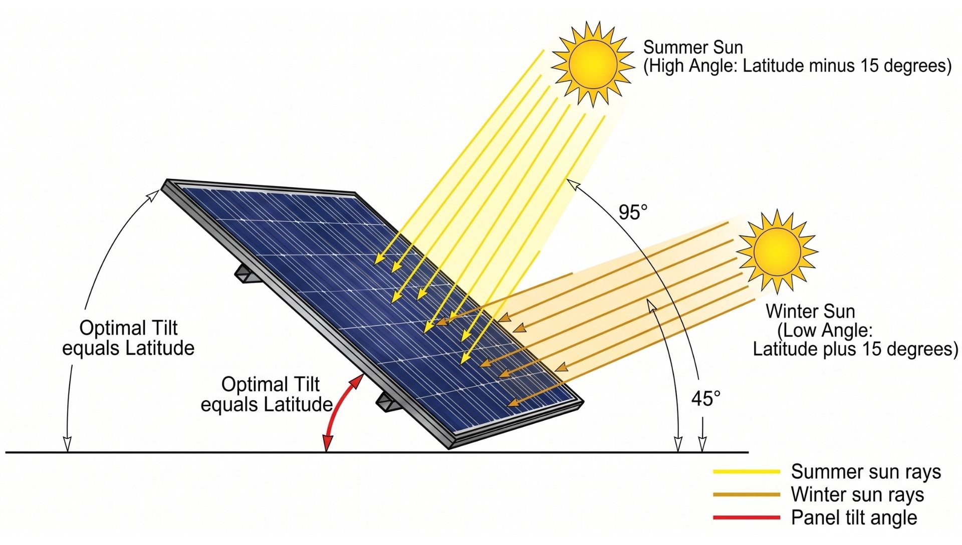
- Azimuth (Direction): In the Northern Hemisphere, true south (180° azimuth) maximizes annual energy output. Southwest and west orientations are also valuable if your utility uses time-of-use (TOU) rates that charge higher prices during late afternoons.
- Array Tilt: Fixed roof-mounted arrays typically match the existing roof pitch (e.g., a 4/12 pitch is roughly 18.4°; a 6/12 pitch is 26.5°). To maximize year-round output, the optimal tilt angle is roughly equal to your geographical latitude.
- Solar Pathfinder / Shade Audit: Even partial shade from a chimney, vent pipe, or tree branch across a single cell can drag down the output of an entire series string. Use digital shade analyzers or observe the roof profile at 9:00 AM, 12:00 PM, and 3:00 PM.
3. Permitting, CAD Drafting & AHJ Approval
Most municipalities (Authority Having Jurisdiction – AHJ) and electric utilities require three core documents before issuing a solar building permit:
- Single-Line Electrical Diagram (SLD): A technical schematic showing panels, wire gauges, conduit sizes, fuses, rapid shutdown switches, inverter specs, and point of interconnection.
- Structural Attachment Plan: Showing rafter spacing, attachment points, rail spans, and wind/snow load calculations.
- Site Plan: An overhead property map indicating panel layout, roof boundaries, and fire department setbacks (typically 36 inches of clearance along ridges and hips for firefighter ventilation paths).
- DIY Tip: You can hire online solar design services (such as GreenLancer or freelance engineers) for $150 to $350 to generate stamped, code-compliant plan sets ready for municipal submission.
4. Step-by-Step Mechanical Installation: Rails and Racking
Once permits are in hand and materials are delivered, mechanical installation begins. Work methodically to maintain straight lines and water-tight penetrations.
[Step 1: Chalk Layout] ──► [Step 2: Rafter Piloting] ──► [Step 3: Flash & Lag Bolt] ──► [Step 4: Level Rails]1: Snap Chalk Grid Reference Lines
- Review your engineering plan for cantilever and rail-spacing dimensions.
- Measure down from the roof ridge to locate the top rail position.
- Measure the distance to the bottom rail position (typically spaced to grip the panels within the inner 25% clamping zone of their length).
- Snap high-visibility chalk lines horizontally across the roof plane.
2: Locate and Mark Rafter Centers
- Locate the rafters along the chalk line using a rubber mallet (listening for solid vs. hollow echoes) or measuring inward from an exposed rafter tail under the eave.
- Drill a small 1/8 in. exploratory pilot hole to verify the center of the structural rafter.
- Mark every attachment point (typically every 48 to 72 inches along the rail, depending on local wind load engineering).
3: Install Flashing Plates and Structural Lag Screws
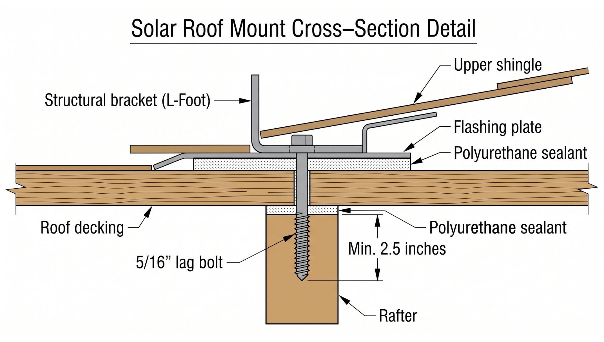
- Gently lift the shingle tab directly above the pilot hole using a flat pry bar (break the sealant bond carefully to avoid tearing old shingles).
- Squirt a generous amount of polyurethane sealant into the pilot hole and across the underside of the aluminum flashing plate.
- Slide the flashing plate up beneath the overlapping upper shingle course so the hole aligns with your pilot mark.
- Place the L-foot bracket on top of the flashing plate.
- Drive a heavy structural lag screw (5/16 in. x 4-1/2 in. with an EPDM sealing washer) down through the L-foot and flashing, embedding it at least 2.5 to 3 inches into solid rafter wood.
- Apply a bead of sealant over the lag head and around the perimeter of the flashing.
4: Mount, Splice, and Level Racking Rails
- Attach aluminum racking rails to the mounted L-feet using the manufacturer’s T-bolts and flange nuts.
- When joining rail segments together, insert internal splice bars and tighten bonding screws to preserve structural strength and electrical ground continuity.
- Use a string line or long level across the top of the rails. Insert leveling shims or adjust the vertical slots on the L-feet to eliminate roof dips, creating a flat plane across the entire array.
5. Electrical Wiring: Strings, Combiners, Grounding & Safety
Electrical installation requires careful wire sizing, correct string matching, and strict adherence to the National Electrical Code (NEC).
[Array DC Strings] ──► [Rooftop Junction / Combiner] ──► [DC Disconnect] ──► [Inverter / Charge Controller]Step 1: Plan String Voltages and Avoid Series Sizing Errors
Solar panels generate DC power. When wired in Series, voltage adds together while amperage stays constant. When wired in Parallel, amperage adds together while voltage stays constant.
Series String Voltage (V_string) = ∑V_panel | Current (I_string) = I_panel
Parallel String Current (I_array) = I_string | Voltage (V_array) = V_string
Cold-Temperature Voltage Surge Calculation
You must ensure that the maximum open-circuit voltage (V_oc) of your string on the coldest morning in your region never exceeds the maximum input voltage rating of your inverter or charge controller (e.g., 500V or 600V DC).
Max Cold V_oc = N x V_oc (STC) x [ 1 + Temp Coeff of V_oc x (T_min – 25°C ]
- N: Number of panels in series (e.g., 10 panels).
- V_oc (STC): Panel rated open-circuit voltage (e.g., 49.5V).
- Temp Coeff: E.g., -0.0028°C (0.28%/°C).
- T_min: Local record low temperature (e.g., -15°C).
Cold V_oc = 10 x 49.5 x [ 1 + (-0.0028) x (-15 – 25) ]
Cold V_oc = 495 x [ 1 + (-0.0028 x -40) ] = 495 x 1.112 = 550.44 V
- Validation: If your string inverter has a 600V maximum input, a 10-panel string producing 550.44V on a -15°C morning is safe and code-compliant.
Step 2: Cable Management and Rooftop Junction Box
- Connect panels in series by clicking positive (+) and negative (-) male/female factory MC4 leads together until they click firmly.
- Use UV-resistant stainless steel wire clips every 12 to 18 inches along the rail channels to secure all excess wire. No wire should ever touch the abrasive roof surface.
- Route the positive and negative homerun leads into a water-tight rooftop junction box (e.g., Soladeck).
- Transition from outdoor-rated 10 AWG PV Wire to standard heat-resistant 10 AWG THHN copper building wire inside the junction box using DIN-rail terminal blocks.
ROOFTOP JUNCTION BOX TRANSITION
| From Array (Exterior) | Outdoor UV-Rated PV Wire |
| Inside Junction Box | DIN-Rail Screw Terminals |
| Down to Inverter (Conduit) | Heat-Resistant THHN Copper |
Step 3: Equipment Grounding and Bonding (NEC 690.43)
Grounding is essential to prevent electrical shock and safely redirect lightning strikes:
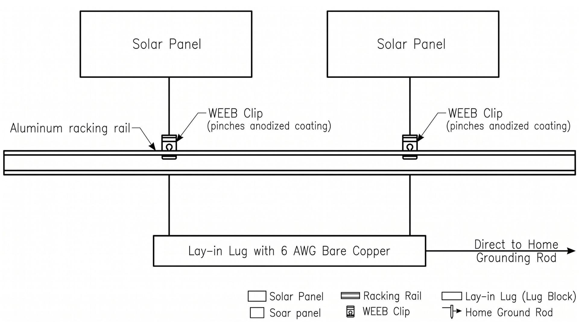
- Module-to-Rail Bonding: Use racking clamps equipped with integrated stainless steel grounding pins (WEEB clips) that pierce through the anodized aluminum coating of the panel frames upon tightening, creating an electrical bond between panel and rail.
- Rail-to-Rail Grounding: Fasten a bare 6 AWG copper ground wire to each rail row using a lay-in grounding lug torqued with stainless hardware.
- System Ground: Run the continuous 6 AWG ground conductor down through the conduit directly to the main electrical service grounding electrode (ground rod) system.
6. Panel Placement & Securing: The Lift and Clamp Protocol
Mounting the modules onto the racking rails requires two people and a strict workflow to avoid drops or cracked cells.
- Set the Bottom Edge Alignment: Clamp a temporary wood block or hook a guide line to the bottom rail to serve as an alignment rest for the first course of panels.
- Install End Clamps on the First Panel: Place the first module squarely on the rails. Slide the aluminum end clamps over the outer frame lip and hand-thread the hex bolts.
- Torque to Manufacturer Specifications: Use your calibrated torque wrench to tighten the end clamps to spec (typically 100 to 120 in-lbs). Check that the module frame sits flat against the rail.
- Insert Mid-Clamps: Slide dual-sided mid-clamps into the rail channel against the first panel. Slide the second panel into place so the clamp bridges both module frames.
- Maintain Expansion Gaps: Ensure an even 0.5 inch gap between all panels to allow for natural thermal expansion during hot summer days.
- Work in Rows: Complete bottom courses first and work upward toward the roof ridge.
7. Testing, Commissioning & Final Inspection Protocol
Never turn on breakers without completing pre-commissioning verification. Follow this structured checklist with a digital multimeter to confirm proper connections:
[1. Visual & Mechanical Audit] ──► [2. Open-Circuit Voc Test] ──► [3. Polarity Verification] ──► [4. Sequential Energization]1. Pre-Power Electrical Verification
- [ ] Visual Inspection: Verify all conduit fittings are tight, weatherheads sealed, and ground lugs secured.
- [ ] Torque Audit: Spot-check 10% of all rail bolts and electrical terminals with a torque wrench.
- [ ] Polarity Check: Set your multimeter to DC Volts. Insert the red lead into the positive array homerun and black lead into the negative homerun. The meter must show a positive voltage number. If the number is negative, your homerun wires are crossed.
- [ ] V_oc String Match: Measure the open-circuit voltage of each string under sunlight. All parallel strings must have voltages matching within 1% to 2% of each other. A larger difference indicates a missing or disconnected panel in one string.
- [ ] Ground Fault Test: Test DC Positive to Ground, then DC Negative to Ground. Both readings should initially display zero or decay quickly to zero volts. A steady voltage reading to ground indicates pinched wire insulation.
2. Sequential System Energization
- Close the rooftop DC isolator/disconnect switch.
- Close the ground-level DC disconnect switch at the inverter input.
- Switch on the main AC backfeed breaker inside the service panel.
- Switch on the inverter’s primary power toggle.
- Monitor Inverter Startup Cycle: Modern inverters observe a mandatory 5-minute safety countdown while checking utility voltage, frequency, and array insulation before synchronizing and exporting power.
8. Summary: 5 Affordable DIY Cost-Saving Strategies
To maximize return on investment while maintaining code compliance, apply these proven procurement and installation strategies:
1. Buy Panels in Pallet Quantities
Buying individual solar panels from retail storefronts incurs shipping penalties. Ordering a full factory pallet (26 to 31 panels) from wholesale distributors cuts freight costs down to 0.35 to 0.50 per watt. Split remaining panels with a neighbor or save them for future expansion.
2. Rent Specialized Tools
Rent heavy hammer drills, 50 ft. scaffolding, or conduit benders from local equipment rental yards for a day or two rather than buying tools you will only use once.
3. Choose Integrated Grounding Hardware
Use modern racking systems (such as IronRidge, Unirac, or SnapNrack) with built-in bonding clips. These eliminate the need to run individual bare copper jumper wires between every panel, saving dozens of hours on the roof and hundreds of dollars in copper wire.
4. Use Microinverters or String Inverters with DC Optimizers Wisely
If your roof has zero shade across the day, a single central string inverter is hundreds of dollars cheaper than outfitting every panel with a microinverter. If you have complex multi-angle roof planes or intermittent shade, choose microinverters to prevent array-wide output loss.
5. Complete the Paperwork Yourself
Do not pay third-party expediters $1,000+ for standard municipal permits. Most local building departments provide simple solar permit checklists. Work directly with municipal plan checkers to make revisions yourself.
By taking a methodical approach to engineering calculations, securing solid structural anchors, and using the right safety and diagnostic tools, your self-installed solar array will operate safely and generate clean, free electricity for decades.
To see a safe rooftop racking and rail installation workflow in action, watch this How to install solar panel roof racking and flashing step-by-step tutorial. It demonstrates how to locate structural rafters, install waterproof flashings, and level aluminum mounting rails safely on composite shingle roofs.