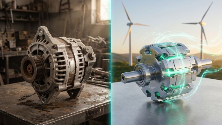
Building a true free energy generator with magnets that creates electricity from nothing is physically impossible. Such a device violates the law of conservation of energy. Permanent magnets cannot spin a rotor indefinitely on their own. They also cannot produce more electrical energy than the mechanical energy you put in. However, you can use permanent magnets and copper coils to build a real electromagnetic generator. This device converts wind, water, or hand-cranked motion into usable electricity.
Viral videos often show “self-running” magnet motors lighting up bulbs without an external power source. Those demonstrations rely on hidden batteries, concealed motors, or stored kinetic energy. Magnets do not contain a harvestable reservoir of fuel. Instead, their magnetic fields act as an essential link in electrical generation. They allow nearly every power plant on Earth to convert mechanical motion into electrical current.
This guide separates perpetual motion myths from electrical engineering reality. You will learn the exact physics of how magnets generate electricity and why self-running motors lock up. Then, you will build a working, low-RPM axial flux magnet generator on your workbench.
Key Takeaways
- No overunity: Permanent magnets produce a static, conservative magnetic field. They act as energy transducers during motion, not as a consumable fuel source.
- Mechanical input is mandatory: Every working magnet generator requires an external prime mover. You need a hand crank, wind turbine, or water wheel to push magnets past copper coils.
- Lenz’s Law creates drag: Drawing electrical current from a generator creates an opposing magnetic field in the coils. This field physically resists the rotation of the rotor.
- Realistic DIY output: A benchtop axial flux generator using N52 neodymium magnets produces 5V to 15V DC and 1W to 10W. This powers LEDs or trickle-charges a small battery, but it cannot power a home.
Looking for a Full-Scale Home Backup Power Blueprint?
Building a benchtop magnet alternator is a great way to learn electromagnetic induction, but a 10W hand-cranked unit won’t lower your monthly electric bill. If you want to skip the trial-and-error and build a practical, low-cost home backup power system using off-the-shelf electrical parts, check out The Energy Revolution System Blueprints. It walks you through exact parts lists, wiring schematics, and step-by-step assembly instructions designed for beginners.
→ Click Here to See the Step-by-Step Energy Revolution Blueprints
Can a Free Energy Generator With Magnets Really Work?
Understanding why a self-running free energy generator with magnets fails requires looking at basic physics. The First Law of Thermodynamics is the law of conservation of energy. It states that energy cannot be created or destroyed in an isolated system. Energy can only transform from one form to another. Therefore, a generator does not create energy; it converts mechanical work into electrical energy.
Why Static Magnetic Fields Cannot Do Net Work
Many inventors try to bypass thermodynamics by arranging neodymium magnets on a rotor and stator at angled intervals. They hope continuous magnetic repulsion or attraction will spin the wheel forever. In physics, a static magnetic field is a conservative vector field. Imagine a ball rolling down a hill. It gains kinetic energy that is completely spent when it climbs an identical hill. Similarly, a magnet pulled toward another magnet gains kinetic energy. That exact amount of energy is consumed when you try to pull it away. The net work done around any closed loop in a static magnetic field is always zero:

In real-world builds, these “magnet motors” quickly reach an equilibrium point, or a magnetic dead spot. At this spot, backward attractive forces exactly balance forward repulsive forces. Even if you spin the rotor by hand, the Second Law of Thermodynamics takes over. Bearing friction, air resistance (windage), and magnetic eddy currents convert that initial momentum into waste heat. Shortly after, the rotor stops completely.
Why Patent Offices Reject Perpetual Motion Machines
Patent offices treat overunity claims with strict skepticism because they contradict established physical laws. The United States Patent and Trademark Office (USPTO) outlines this in its Manual of Patent Examining Procedure (MPEP § 2107.01). Applications for perpetual motion or “overunity” machines claim more than 100% efficiency. The USPTO routinely rejects these applications under 35 U.S.C. 101 for lack of utility.
Standard patent applications rely only on written descriptions and schematics. In contrast, the USPTO requires perpetual motion applicants to submit a certified, working physical model. This model must withstand independent laboratory testing. To date, no magnetic overunity device has ever passed this verification.
How Magnet Generators Work: The Physics of Electromagnetic Induction
Magnets cannot give you energy for nothing, but they are the core component of electromagnetic induction. Michael Faraday discovered this principle in 1831. Electromagnetic induction generates an electrical voltage across a conductor by exposing it to a changing magnetic field.
Faraday’s Law and Moving Magnetic Flux
A stationary magnet sitting next to a stationary copper wire generates zero electricity. The strength of the magnet does not change this rule. Voltage is only induced when the magnetic flux passing through a coil of wire changes over time. Faraday’s Law of Induction quantifies this exact relationship:

- ℰ (Electromotive Force): The induced voltage, measured in volts (V).
- N (Number of Turns): The number of individual wire loops in your copper coil. Doubling the turns doubles the induced voltage.
- ΦB (Magnetic Flux): The magnetic field strength (B, in Teslas) multiplied by the coil area (A, in square meters) perpendicular to the field.
- dt (Change in Time): How rapidly the magnetic field changes as the magnet sweeps past the coil. Spinning the rotor twice as fast cuts the sweep time in half. This doubles both the output voltage and the AC frequency.
Lenz’s Law and Magnetic Braking Under Load
Notice the negative sign in Faraday’s equation. That minus sign represents Lenz’s Law, which explains why “free energy” generator schemes fail under load. Lenz’s Law states that an induced current always creates a secondary magnetic field. This secondary field opposes the change in flux that produced it.
When your generator spins with nothing connected to the output wires (an open circuit), no current flows. The rotor spins freely, experiencing only minor bearing friction. The instant you connect a load—such as an LED, resistor, or battery—current flows through the copper coils. Each coil immediately becomes an electromagnet. Its polarity repels the approaching rotor magnet and attracts the departing rotor magnet.
You can feel this effect physically on a hand-cranked generator. If you spin the crank and short-circuit the output wires together, the crank suddenly becomes hard to turn. To get electrical watts out, you must push harder against this magnetic braking torque.
| Feature | “Free Energy” Magnet Motor Myth | Real Electromagnetic Generator |
|---|---|---|
| Energy Source | Claims to extract energy from static magnets | Converts external mechanical work (wind, water, crank) |
| Efficiency | Claims greater than 100% (“overunity”) | Typically 50% to 90% depending on build precision |
| Effect of Adding Load | Claims to maintain speed or accelerate | Increases mechanical resistance (Lenz’s Law torque) |
| Realistic Output | Claims to power a whole house for free | DIY benchtop unit yields 1W–15W; scales with input torque |
| Scientific Basis | Violates 1st & 2nd Laws of Thermodynamics | Governed by Faraday’s Law and Lenz’s Law |
How to Build a DIY Magnet Generator (Axial Flux Alternator)
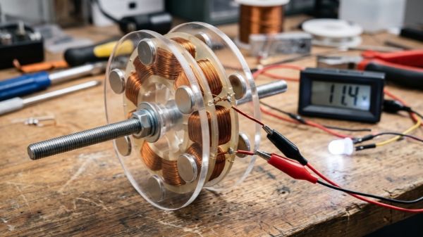
Instead of chasing a non-working magnet motor, you can build a functional single-phase axial flux alternator. In an axial flux design, flat disc rotors carry neodymium magnets. These rotors spin parallel to a stationary flat ring of copper coils called the stator. This design uses an air-core stator with no iron teeth. Because there is no iron core, it eliminates “cogging torque” (the bumpy magnetic locking between magnets and iron). As a result, the rotor is easy to spin by hand or with a small wind turbine blade.
Materials and Tools Needed
Materials:
- 16x Neodymium Block or Disc Magnets: Grade N42 to N52 (e.g., 20mm diameter × 5mm thick discs, or 25mm × 10mm × 5mm blocks).
- Magnet Wire (Enameled Copper Wire): 24 AWG to 28 AWG, approximately 150 feet (45 meters).
- Rotor Discs (2x): 120mm (4.75-inch) diameter circles cut from 6mm (1/4-inch) acrylic, polycarbonate, or birch plywood. Mild steel plates work even better as a magnetic “back-iron” to increase flux density, though acrylic is easier to drill.
- Stator Plate (1x): 150mm × 150mm (6-inch × 6-inch) sheet of 6mm acrylic or plywood.
- Threaded Shaft & Hardware: One 8mm (or 5/16-inch) threaded rod (200mm long), 2x flanged ball bearings, 6x hex nuts, and washers.
- Rectifier Components: 4x 1N5819 Schottky diodes (chosen for a low 0.3V forward voltage drop) and one 1,000µF 25V electrolytic capacitor.
- Adhesive: High-strength two-part epoxy and cyanoacrylate (superglue).
Tools:
- Drill with bit assortment and hole saw (or jigsaw).
- Digital multimeter (capable of measuring AC/DC voltage and current).
- Soldering iron and rosin-core solder.
- 220-grit sandpaper or hobby knife (for stripping magnet wire enamel).
- Permanent marker and compass.
1. Prepare the Rotor Discs and Mount the Magnets
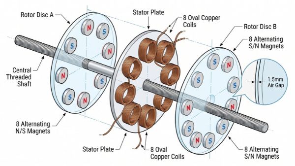
- Lay Out and Mark the Rotor Discs
Use a compass to draw a circle with a 40mm radius centered on both 120mm rotor discs. Divide this circle into 8 equal segments spaced 45 degrees apart. Drill a centered 8mm hole through both discs so they fit snugly onto your threaded shaft. - Mount Magnets in Alternating Polarity (N-S-N-S)
Identify the poles of your neodymium magnets and mark the North faces with a permanent marker. Glue 8 magnets onto the marked positions of the first rotor disc. Alternate their poles around the circle: North up, South up, North up, South up (4 North, 4 South). On the second rotor disc, glue the remaining 8 magnets in the opposite orientation. When the two discs face each other, opposite poles must attract across the air gap. A North face on Disc A must directly face a South face on Disc B. Allow the two-part epoxy to cure for 24 hours.
2: Wind and Wire the Copper Stator Coils
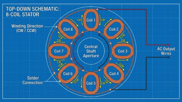
- Wind the 8 Copper Stator Coils
Create a simple winding jig by driving two dowels or bolts spaced 15mm apart into a scrap piece of wood. Leave a 10cm lead wire free. Wind 100 to 150 tight, neat turns of 26 AWG enameled copper wire around the jig. The center opening of the oval coil should match the size of one magnet. Secure the coil with drops of superglue or electrical tape before sliding it off the jig. Repeat this process until you have 8 identical coils with the exact same number of turns. - Arrange and Wire the Stator Coils in Series
Draw an identical 40mm-radius circle with 8 positions (45 degrees apart) on your square stator plate. Cut a 35mm hole in the center so the shaft and bearings can pass through untouched. Because the rotor magnets alternate polarity (N-S-N-S), adjacent coils experience opposite magnetic fields at the same time. To make their voltages add together instead of canceling out, alternate the winding direction of each coil. Place Coil 1 clockwise, Coil 2 counter-clockwise, Coil 3 clockwise, and continue around the circle. Scrape the enamel insulation off the wire ends using sandpaper. Solder the end of Coil 1 to the start of Coil 2, continuing around all 8 coils until two main output leads remain. Verify electrical continuity with your multimeter before epoxying the coils flat onto the stator board.
3: Assemble the Generator and Rectify the Output
- Assemble the Shaft, Bearings, and Air Gap
Press your flanged ball bearings into a wooden base frame that holds the stator plate stationary in the middle. Slide the threaded rod through the bearings. Mount Rotor Disc A on one side of the stator and Rotor Disc B on the other side. Use hex nuts and washers on the threaded shaft to lock their positions. Crucial alignment step: Rotate Disc B until its magnets strongly attract the opposite magnets on Disc A directly through the coils. Tighten the locking nuts once aligned. Adjust the nuts so each rotor sits 1.5mm to 2mm away from the copper coils without rubbing. A smaller air gap produces stronger magnetic flux ($B$) cutting the wire. - Build the Bridge Rectifier and Test Output
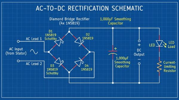
Because the magnets alternate North and South, your stator produces Alternating Current (AC). Connect your multimeter (set to AC Volts, 20V range) to the two stator leads. Give the rotor a brisk spin by hand. You should see 3V to 12V AC depending on your rotation speed. To convert this into Direct Current (DC) for LEDs or battery charging, solder the four 1N5819 Schottky diodes into a full-wave bridge rectifier. Finally, wire the 1,000µF capacitor in parallel across the DC positive and negative outputs to smooth out voltage ripples.
Realistic Performance, Efficiency, and Limitations
Testing a DIY magnet generator with a multimeter requires comparing two metrics: open-circuit voltage (V_oc) and loaded power (P). Understanding this difference prevents disappointment.
- Expected Voltage: Spinning the 8-pole rotor at 300 to 600 RPM yields 5V to 14V open-circuit voltage. You can reach this speed with a geared hand crank or a stiff breeze on a 3-foot turbine blade.
- Expected Current and Power: Thin 26 AWG copper wire has noticeable internal electrical resistance (around 4 to 6 ohms across all 8 coils in series). This resistance limits maximum current to roughly 0.2A to 0.8A. Under a matched load, expect 1 Watt to 8 Watts of continuous electrical power (P = V x I).
Want to Power Actual Household Appliances Instead of Just LEDs?
As we saw above, an un-geared 8-pole benchtop generator is limited to a few watts of output. Scaling a system up to run 120V household electronics, lights, or emergency appliances requires proper coil sizing, capacitor banks, and voltage regulation. Instead of guessing the math or buying expensive commercial solar arrays, you can follow a complete, tested assembly guide. The Energy Revolution System gives you illustrated diagrams and video walkthroughs to put together a compact, budget-friendly auxiliary power unit in a single afternoon.
→ Watch the Energy Revolution System Presentation & Get the Plans
Why Efficiency Drops Under Load
Even commercial generators cannot convert 100% of mechanical input into electricity. In a DIY build, energy losses come from four main areas:
- Copper Losses: Every copper coil has internal resistance (R). As current (I) flows through the windings, electrical energy dissipates directly as heat inside the wire. Using thicker wire (such as 20 AWG) reduces resistance and increases current output. However, thicker wire requires a larger stator to fit the same number of turns.
- Rectifier Voltage Drop: Standard silicon diodes (like the 1N4007) consume about 0.7V per diode. A full bridge rectifier eats up 1.4V of your generated output before it ever reaches your load. Using Schottky diodes reduces this loss to about 0.6V total.
- Flux Leakage and Air Gap Losses: Magnetic field strength drops off rapidly with distance. An air gap of 5mm instead of 1.5mm can cut your voltage output by more than half.
- Mechanical Friction and Eddy Currents: Bearing drag and air resistance slow the rotor down. Furthermore, placing aluminum or unlaminated copper plates too close to spinning magnets causes magnetic drag. The changing fields induce circular currents (eddy currents) inside the metal plate, acting as a brake and generating waste heat.
What this project is good for: Lighting arrays of 5mm or 1W LEDs, demonstrating Faraday’s Law in a classroom, trickle-charging a 5V USB power bank (with a buck-boost voltage regulator), or acting as a wind speed sensor.
What it cannot do: It cannot run household appliances, power a space heater, or drive an electric motor that spins its own shaft in a self-sustaining loop.
Safety Precautions When Working With Neodymium Magnets
Rare-earth neodymium-iron-boron (NdFeB) magnets are much stronger and more hazardous than standard ferrite fridge magnets. Follow these safety protocols during assembly:
- Pinch and Impact Hazards: Two N52 magnets released within a few inches of each other will slam together rapidly. This impact can cause severe blood blisters or skin lacerations. Slide magnets apart laterally off the edge of a wooden workbench rather than prying them straight apart. Keep your fingers clear of the gap between Rotor A and Rotor B during assembly.
- Shattering and Eye Protection: Neodymium magnets are brittle ceramics coated in thin nickel-copper-nickel plating. If they snap together freely, they can chip or shatter and launch razor-sharp metallic splinters. Always wear ANSI Z87.1-rated safety glasses when handling uncovered magnets.
- Pacemakers and Medical Implants: Strong magnetic fields can deactivate or switch the operating mode of implantable cardioverter-defibrillators (ICDs) and pacemakers. Keep neodymium magnets at least 12 inches (30 cm) away from any implanted medical device.
- Centrifugal Force Hazards: Never spin a homemade rotor using a high-speed power drill or angle grinder. At high RPMs, glue bonds can fail and turn a detached magnet into a dangerous projectile. High-speed rotors require recessed magnet pockets and a fiberglass or Kevlar retaining sleeve.
Troubleshooting Common DIY Magnet Generator Problems
If your finished generator fails to register voltage on your multimeter or produces low power, inspect these four failure points:
Zero or Near-Zero Voltage Output (less than 0.5V)
- Cause: Two or more coils are wound or wired in the same direction next to alternating magnets. Their induced voltages cancel each other out (+1.5V – 1.5V = 0V).
- Fix: Disconnect the series solder joints and test each individual coil with an AC multimeter while spinning the rotor. Re-solder the connections so that each pair adds voltage together.
Open Circuit (Infinite Resistance / “OL” on Multimeter)
- Cause: Enameled magnet wire is coated in a tough polyurethane varnish that looks like bare copper. Soldering over unstripped enamel creates a cold joint with no electrical contact.
- Fix: Scrape the wire leads thoroughly with sandpaper. Alternatively, burn off the enamel with a lighter flame and clean the soot with isopropyl alcohol before re-soldering.
Weak Voltage Output Despite Correct Wiring
- Cause: The air gap between the rotor magnets and stator coils is too wide. Alternatively, the two rotor discs may be aligned with like poles facing each other (N-N instead of N-S).
- Fix: Verify that the two rotor discs strongly pull toward each other across the stator. Adjust the shaft nuts so the magnets clear the coils by no more than 1.5mm to 2mm.
Rotor Rubs or Wobbles Against the Stator
- Cause: Strong axial magnetic attraction between Rotor A and Rotor B is flexing the rotor discs inward toward the stator.
- Fix: Upgrade from thin acrylic or plywood to stiffer 6mm polycarbonate or steel backing plates. Place wide fender washers on both sides of each rotor disc to prevent flexing along the shaft.
Practical Alternatives for Real “Free” Energy
You cannot extract energy from magnets alone. However, ambient energy exists all around us as sunlight, wind, moving water, and waste heat. If your goal is to lower your electricity bill or build an off-grid power source, these four renewable technologies capture genuine environmental energy:
1. Solar Photovoltaic (PV) Systems
Solar panels use semiconductor cells to convert photons from sunlight directly into DC electricity via the photovoltaic effect. They require zero moving parts.
- Pros: Extremely reliable, silent, and modular (from a 10W camping panel to a 10kW rooftop array). Solar offers the lowest cost per watt over a 25-year lifespan.
- Cons: Produces zero power at night. Output drops by 70%–90% under heavy cloud cover, requiring battery storage for 24-hour off-grid use.
2. Small-Scale Wind Turbines
A wind turbine uses aerodynamic blades as the prime mover to spin a permanent magnet axial flux alternator. Many DIY turbines use the exact same N-S-N-S neodymium geometry built in this guide, scaled up to 24V or 48V.
- Pros: Generates power day and night whenever wind speeds exceed the cut-in threshold (typically 7–9 mph).
- Cons: Highly sensitive to turbulence from trees and buildings. It requires a tall tower and periodic maintenance for bearings and blades.
3. Micro-Hydro Generators
A property with a year-round stream and a consistent vertical drop (“head”) can run a micro-hydro system. A Pelton or Turgo water wheel coupled to a permanent magnet alternator is the most productive off-grid power source available.
- Pros: Generates continuous power 24 hours a day, 365 days a year. It requires much smaller battery banks than solar or wind.
- Cons: Strictly site-dependent and often requires environmental water permits. Intake screens must be cleared regularly of leaves and sediment.
4. Human-Powered Kinetic Generators
Hand cranks and pedal-powered bicycle generators couple human muscle output to a geared permanent magnet DC motor or alternator.
- Pros: Works anywhere on demand regardless of weather. It is ideal for emergency radios, flashlights, and physics education.
- Cons: Human physical output is modest. A fit adult pedaling a stationary bicycle can sustain roughly 75W to 100W for an hour. This highlights how much mechanical effort goes into generating a single kilowatt-hour of electricity.
Ready to Slash Your Power Bill Without Spending $15,000 on Rooftop Solar?
Commercial solar and wind installations take years to pay for themselves. If you want an affordable, DIY way to generate supplemental electricity and protect your family during grid blackouts, you don’t need an engineering degree.
- Complete, beginner-friendly wiring schematics and parts list
- Uses inexpensive components available at local hardware or electronics stores
- Compact footprint—fits in a garage, shed, or closet
- Backed by a 60-day money-back guarantee
👉 Get Instant Access to The Energy Revolution System Here
Frequently Asked Questions (FAQ)
Why do magnets eventually stop spinning in a magnet motor?
Static magnetic fields are conservative. The energy gained when two magnets attract or repel equals the energy required to move them past the next pole. A magnet-only rotor quickly locks into a balanced magnetic equilibrium point. Meanwhile, bearing friction and air resistance dissipate any initial hand-spun momentum as heat.
Do neodymium magnets lose their strength when used in a generator?
No, generating electricity does not drain or “use up” a magnet’s field. The magnet only acts as a pathway to convert your mechanical push into electrical current. Under normal operating temperatures (below 80°C/176°F for standard N-grade magnets), neodymium magnets lose less than 1% of their magnetization over a decade.
Can you use an old DC motor as a magnet generator?
Yes, permanent magnet DC (PMDC) motors found in treadmills, radiator fans, and cordless drills make great DIY generators. When you spin the shaft of a PMDC motor externally, it acts as a dynamo. It outputs DC voltage proportional to its RPM. Avoid induction motors or universal motors without permanent magnets.
How many watts can a small DIY magnet generator produce?
A tabletop hand-cranked or small wind-driven axial flux generator built with 16 neodymium magnets typically outputs 1 to 15 watts under load. Scaling up to 100–500 watts requires larger N52 magnets, thick 12–16 AWG copper windings, steel rotor plates, and a high-torque wind or hydro rotor.
Why does a generator become harder to turn when you connect a load?
This resistance is caused by Lenz’s Law. When an electrical load completes the circuit, current flows through the stator coils and turns them into electromagnets. The magnetic field created by those coils directly opposes the spinning rotor magnets. Consequently, you must apply more mechanical torque to keep the shaft turning.
Are viral “free energy generator” videos on YouTube real?
No. Viral videos showing self-running magnet wheels or extension cords plugged into themselves are stage illusions. Creators hide button-cell batteries inside hollowed-out wooden bases, conceal thin wires beneath tables, or blow compressed air off-camera. These tricks spin the rotor to fool viewers for ad revenue.
Conclusion
The dream of a self-running free energy generator with magnets is a physical impossibility. Still, the real science of electromagnetic induction is far more rewarding to master. Permanent magnets do not violate the conservation of energy, nor can they power a home out of thin air. Instead, they serve as highly efficient transducers. They allow you to turn wind, flowing water, or mechanical motion into clean, measurable electricity.
By building this 8-pole axial flux alternator, you can observe Faraday’s Law and Lenz’s Law firsthand on your workbench. Start by measuring your baseline AC and DC output with a multimeter. Next, pair your alternator with a simple PVC wind turbine blade or Pelton water wheel to harvest genuine renewable energy from your environment.
Your Next Step: Take Your DIY Power Project to the Next Level
Once you understand how coils, magnets, and capacitors work together, you have the foundation to build a serious off-grid backup system. Don’t wait for the next grid outage or utility rate hike to start preparing. Grab the complete schematics, video guides, and parts list inside The Energy Revolution System and start building a reliable home energy setup this weekend.
References
- Feynman, R. P., Leighton, R. B., & Sands, M. (1964). The Feynman Lectures on Physics, Vol. I: Mainly Mechanics, Radiation, and Heat (Chapter 4: Conservation of Energy) & Vol. II: Mainly Electromagnetism and Matter (Chapter 17: The Laws of Induction). California Institute of Technology.
- United States Patent and Trademark Office (USPTO). Manual of Patent Examining Procedure (MPEP), Section 2107.01: General Principles Governing Utility Rejections (Inoperative Inventions / Perpetual Motion under 35 U.S.C. 101).
- U.S. Department of Energy (DOE) – Office of Energy Efficiency & Renewable Energy (EERE). How Do Wind Turbines Work? and Small Wind Guidebook.
- National Institute of Standards and Technology (NIST). SI Units – Electric Current and Electromagnetism.
- OpenStax / Rice University. University Physics Volume 2, Chapter 13: Electromagnetic Induction (Faraday’s Law and Lenz’s Law).